
Engineered Solutions for Modern Data Center Infrastructure
Reliable Performance for Next-Generation Compute Workloads
- Home

- Electronics Assembly
- Data Centers
- Data Center Server Racks
Data Center Server Racks
At the core of every modern data center is the server rack. It is a standardized and space-efficient framework that houses and organizes critical IT hardware. Most racks follow a 19-inch width standard and act as the backbone of high-density infrastructure. They allow enterprises to increase computing performance while keeping space, power, and cooling under control.
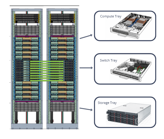
Compute Tray
The Data Center Compute Tray is a purpose-built platform engineered to simplify rack-scale deployments, upgrades, and maintenance cycles. Each tray supports a configurable mix of compute modules including high-density CPUs, GPUs, AI accelerators, and memory expansion units, while maintaining a standardized mechanical, electrical, and thermal interface across configurations. Precision-shaped airflow channels, isolated hot/cold paths, and integrated cold-plate or hybrid cooling options ensure repeatable thermal performance, even under extreme AI and HPC workloads.
Designed for both new hyperscale builds and retrofit modernization projects, the compute tray reduces mean time to repair (MTTR) through tool-less serviceability, front-access module replacement, and uniform cabling architecture. Its chassis incorporates high-stiffness structural elements to support large cold plates, heavy accelerators, and next-generation power delivery modules without warping or alignment loss. With built-in telemetry for power, temperature, and reliability metrics, the tray serves as a scalable building block that enables operators to increase density, improve thermal efficiency, and accelerate deployment of AI-optimized data center infrastructure.
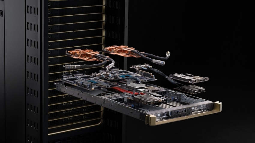
Inside a Compute Tray
CPUs provide the tray’s general-purpose compute backbone.
Key technical functions:
- Task scheduling and orchestration for heterogeneous GPU compute nodes.
- High memory bandwidth management through multi-channel DDR5 or HBM interfaces.
- I/O coordination across PCIe Gen5/Gen6 fabrics, NVMe storage, and networking.
- Low-latency control paths for distributed AI workloads.
GPUs, TPUs, or dedicated AI accelerators provide the bulk of computational throughput.
Across training and inference environments, accelerators deliver:
- Massive parallel processing via thousands of CUDA/streaming cores or matrix engines.
- High-bandwidth memory (HBM2E / HBM3 / HBM3E) for rapid parameter loading.
- Scalable interconnects such as NVLink, NVSwitch, or CXL enabling multi-GPU workloads.
- Tensor and FP8/FP16/INT8 compute needed for AI, LLM, and simulation tasks.
The GPU block is the highest heat-intensity zone of the tray due to continuous high-utilization workloads.
The interconnect links CPUs, GPUs, storage, and network modules through a high-speed backplane.
It enables fast data exchange using PCIe, NVLink, or similar fabrics to keep all compute modules synchronized.
To prevent performance bottlenecks, compute trays integrate advanced data fabrics:
- PCIe Gen5/Gen6
- CXL 2.0/3.0 coherent memory sharing
- NVLink / NVSwitch for multi-GPU clustering
- 100G/200G/400G Ethernet or InfiniBand for rack-scale fabric
These interconnects enable synchronized compute operations across accelerators and multi-node clusters.
High-Heat Components: CPUs & GPUs
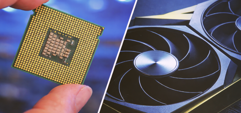
Within a compute tray, CPUs and GPUs are the primary sources of thermal load, driving most of the heat dissipation requirements. Their high power densities, compact die areas, and continuous high-utilization operation make them the central focus of data center thermal design. Modern high-performance accelerators operate at extreme compute densities, integrating billions of transistors switching at high frequency, which creates localized hot spots that demand precise cooling solutions.
Key Contributors to Thermal Increase
High Power Draw
- CPUs: 250 W – 500 W (e.g., Intel Xeon Sapphire Rapids, AMD EPYC Genoa/Bergamo)
- GPUs: 350 W – 1000 W (e.g., NVIDIA H100, H200, B200; AMD MI300)
Small Die Area / High Local Heat Flux
- CPUs: 50 – 100 W/cm²
- GPUs & HBM Stacks: 100 – 150 W/cm², with hot spots significantly higher
High-Bandwidth Memory (HBM) Placement
- Stacks of HBM soldered close to the GPU die create localized heat pockets.
- Proper thermal interface material (TIM) coverage is critical to ensure stable operation.
CPU Temperature Profile
| Condition | Temperature Range |
|---|---|
| Typical steady-state (under load) | 65°C – 85°C |
| High utilization / sustained turbo | 85°C – 90°C |
| Maximum junction temperature (Tj max) | ~95°C – 100°C* |
| Throttle onset | 90°C – 95°C |
*AMD EPYC CPUs allow up to ~95°C; Intel commonly limits below 100°C.
GPU Temperature Profile
| Condition | Temperature Range |
|---|---|
| Typical steady-state | 70°C – 85°C |
| AI training / full utilization | 80°C – 90°C |
| Maximum junction temperature (Tj max) | 90°C – 100°C |
| HBM temperature limit | 85°C – 95°C |
*Exceeding the HBM temperature limit can severely degrade memory stability and reduce system reliability.
CPUs & GPUs in the Market
Modern data center and AI workloads rely on a mix of high-performance CPUs and GPUs/AI accelerators. Each processor type has distinct power profiles, heat densities, and thermal management challenges. The tables below summarize the typical power ranges, maximum thermal limits, and special considerations engineers should account for when designing cooling solutions for these processors.
High-Performance GPUs / AI Accelerators
| Accelerator Model | Typical Power (TBP) | Max Power Profile | Tj Max | Notes |
|---|---|---|---|---|
| NVIDIA H100 (SXM5) | 700W | Up to 750W | ~100°C | Used in DGX/HGX systems; heavy HBM heat flux |
| NVIDIA H200 (SXM5) | 700–800W | Up to 1000W | ~100°C | HBM3e increases memory thermals |
| NVIDIA B200 (Blackwell) | 800–1000W | Up to 1200W | ~100°C | Extremely high heat density; advanced cold plates required |
| AMD Instinct MI300A | 600W | — | ~95–100°C | APU architecture with CPU+GPU increases heat concentration |
| AMD Instinct MI300X | 750W | Up to 850W | ~95–100°C | 192GB HBM3 produces significant hotspot behavior |
High-Performance CPUs
| CPU Model | Typical Power (TDP) | Max Turbo Power | Tj Max | Notes |
|---|---|---|---|---|
| Intel Xeon Sapphire Rapids (4th Gen) | 270W | ~350W | ~90–95°C | High memory-channel density raises heat flux |
| Intel Xeon Emerald Rapids (5th Gen) | 350W | ~420W | ~90–95°C | Higher core counts push thermal headroom |
| AMD EPYC 9654 (Genoa) | 360W | ~400W | ~95°C | Dense chiplet layout → localized hotspots |
| AMD EPYC Bergamo (97x4 series) | 360W | ~400W | ~95°C | Cloud-optimized core count increases sustained heat |
Thermal Interface Materials for CPUs and GPUs
Solstice Thermal Interface Solutions
Modern compute trays integrate CPUs and GPUs that operate at extreme thermal loads, often exceeding 350W for CPUs and 700–1200W for GPUs and AI accelerators. At these power levels, device junction temperatures can reach 90–100°C, while silicon hot spots can spike beyond 110°C if not properly managed.
| Thermal / Mechanical Condition | Scenario | Recommended Solstice TIMs | Why This TIM Fits |
|---|---|---|---|
| Extreme Heat Load from High-Power CPUs/GPUs (300–700W modules) | H100, MI300, Gaudi, EPYC Genoa setups generating very high localized heat; needing low bondline & stable conductivity. | PTM6000, PTM7900, PTM7950 | High thermal conductivity (6–8 W/m·K), phase-change behavior ensures minimal thermal resistance at high loads. |
| High Contact Pressure Interfaces (30–150 psi) | LGA CPU sockets, GPU cold plates requiring material that flows without pump-out. | PTM7900, PTM7950 | Excellent mechanical stability under clamping pressure; optimized for thin BLT and uniform wet-out. |
| Thermal Cycling (−40°C to 125°C) | Systems powering up/down frequently (AI training clusters, test benches). | PTM6000, PTM7950, TGP3500PT | Superior fatigue resistance, minimized cracking/voiding under repetitive expansion/contraction. |
| Low Contact Pressure or Uneven Surfaces | Large cold plates, uneven heat spreaders, warped substrates. | TGP3500PT, TGP6000PT, TGP7000 Series | Conformable putty design absorbs surface irregularities and maintains contact without pressure. |
| Large Gap Fills (0.3–3.0 mm) | Power converters, accelerators, VRMs, memory banks requiring reliable gap bridging. | TGP3500PT / 3510PT / 6000PT | Soft, thixotropic filler system allows compression while maintaining conductivity and stability. |
| High-Throughput Manufacturing / Automated Assembly | Robotic dispensing, stencil/jet printing, high-volume module production. | PTM7900, PTM7950 | Smooth rheology, fast phase-change wetting, excellent print/dispense behavior. |
| Silicone-Sensitive Environments (optics, sensors, automotive) | Avoiding silicone migration or contamination. | PTM7000 Series (silicone-free PCM) | Zero silicone bleed-out; stable long-term interface. |
| Electrically Sensitive Zones (VRM, power modules) | Need isolation + thermal performance. | TGP Series (non-conductive) and PTM6000/PTM7900 | Very high dielectric strength & high volume resistivity. |
| High Mechanical Shock / Vibration | Edge servers, automotive ECUs, or rugged compute hardware. | TGP3500PT / 6000PT, PTM7950 | Putties and high-viscosity PCMs resist cracking and maintain long-term adhesion. |
| High Power-Cycling Reliability (steady heavy load → idle → peak) AI workloads | AI inference/training clusters with fluctuating thermal loads. | PTM7900, PTM7950 | Engineered for stable thermal impedance over thousands of cycles. |
| Ultra-Thin Bondline Requirement (<20–50 μm) | Direct cold-plate interfaces, high watt density chips. | PTM6000, PTM7900 | Flow characteristics enable uniform thin film formation at operating temperature. |
| Maximum Thermal Performance for Liquid Cooling Blocks | Direct-to-chip cold plates on GPUs/CPUs. | PTM7950, PTM7900 | Designed for next-gen direct liquid cooling, excellent wet-out and conductivity. |
AI Server Compute Board TIMs Usage
| Board Section | Component Example | Recommended TIMs | Category |
|---|---|---|---|
| CPU Zone | Grace CPU | PCM45F, PTM6000, PTM7900, PTM7950 | Phase-Change Materials |
| GPU Zone | Hopper GPU w/ HBM | PCM45F, PTM6000, PTM7900, PTM7950 | Phase-Change Materials |
| Peripheral Zone | BIOS Chip, VRM banks, small packages | TGP3500PT, TGP6000, TGP8000, TGP6000PT, TGP8000PT | Gap Pads & Putty Pads |
Solutions for Data Center Cooling
Switch Tray
The Data Center Switch Tray is a networking platform engineered to deliver predictable low-latency connectivity and resilient packet distribution across rack-scale or cluster-scale environments. Built for modern AI fabrics, hyperscale compute clusters, and high-performance cloud networks, the switch tray integrates top-of-rack (TOR), middle-of-row (MOR), or fabric interconnect modules into a standardized mechanical and thermal framework.
A switch tray is a specialized modular platform in modern data centers, designed to deliver high-bandwidth, low-latency network connectivity across rack-scale or cluster-scale environments. Unlike compute or storage trays, which focus on processing or data persistence, the switch tray’s primary role is to move data efficiently and reliably between servers, accelerators, and storage nodes, ensuring smooth operation of AI workloads, HPC clusters, and large-scale cloud applications.
Core Functions
Switch trays integrate multiple networking modules—including top-of-rack (TOR), middle-of-row (MOR), or fabric interconnect switches—into a standardized frame that ensures mechanical stability, thermal efficiency, and electrical reliability. They are capable of supporting modern high-speed protocols such as 100G, 200G, 400G, 800G Ethernet, as well as NDR/HDR InfiniBand, providing the necessary bandwidth and deterministic performance for GPU clusters, disaggregated storage, and latency-sensitive workloads.
Key Features and Architecture
- Supports multiple switch ASIC generations (Broadcom Tomahawk, Marvell Teralynx, NVIDIA Spectrum, or InfiniBand switches).
- Allows flexible configuration of port counts, fiber/copper breakouts, and optical transceiver types (QSFP-DD, OSFP).
- Hot-swappable modules for rapid in-rack deployment and maintenance.
Switch silicon and optical modules generate high localized heat (typ. 12–25W per OSFP module, 200–350W per switch ASIC).
The tray integrates:
- Directed front-to-back airflow channels
- Independent cooling zones for ASIC, optics, and PSU
- High-static-pressure fans with adaptive RPM control
- Mechanical baffling to eliminate airflow recirculation
- Low-loss PCB materials on the switch chassis (<0.005 dielectric loss tangent)
- Backplane connectors supporting 112G PAM4 signaling
- Crosstalk isolation structures for increased eye-margin stability
- Precision cable management for fiber and DAC routing
Ensures stable traffic under heavy east-west and north-south data center loads.
Dual PSUs with load sharing
Redundant fan modules
In-chassis monitoring for:
- Temperature maps
- Airflow vectors
- Voltage rails
- Error correction counters
Secure management protocols (OpenBMC, RDE, Redfish)
Commercial Switch ASICs with Solstice TIMs
Modern data center networks rely on high-performance switch ASICs to deliver massive throughput while maintaining low latency and reliability. These ASICs generate substantial heat due to dense logic, high-frequency signaling, and tightly packed SerDes lanes. Proper thermal management is critical to ensure consistent performance, long-term reliability, and minimal signal degradation. Thermal interface materials (TIMs) play a key role in bridging the gap between the ASIC die and the heatsink or cold plate. Selecting the right TIM depends on power class, die size, hotspot distribution, and mechanical constraints. The table below summarizes common commercial switch ASICs, their thermal characteristics, and recommended CAPLINQ Solstice TIM solutions for optimal performance.
| Switch ASIC | Power Class | Packaging & Surface Notes | Thermal Needs | Recommended CAPLINQ TIM |
|---|---|---|---|---|
| Broadcom Tomahawk 5 (51.2 Tbps) | 280–350W | Very large die; high flatness requirement; thin BLT | High conductivity + phase stability | PTM7950 (PCM, best for >250W ASICs), PTM7900 (high-conductivity PCM) |
| Broadcom Tomahawk 4 (25.6 Tbps) | 200–260W | Medium-high heat density; uniform compression needed | Thin BLT, reliable interface for long cycles | PTM6000 / PTM7900 |
| Marvell Teralynx 10 | 160–240W | Dense SerDes placement; hotspot regions | Conformable TIM with high conductivity | PTM6000, TGP6000PT (if gap-fill needed) |
| NVIDIA Spectrum-4 (51.2 Tbps) | 300–350W | Large ASIC + retimer ICs; high data rate noise sensitivity | Very low thermal resistance | PTM7950 |
| NVIDIA Spectrum-X (Ethernet for AI, with BlueField) | 200–300W (combined modules) | Multiple ICs: Switch + DPU + PHY | Mixed BLTs and mixed surfaces | PTM6000 on ASICs, TGP3500PT or 3510PT for gap regions |
| NVIDIA Quantum-2 InfiniBand (NDR) | 260–300W | Extremely tight thermal envelope; optical cages adjacent | High-compression PCM + excellent mechanical stability | PTM7950 |
| Older HDR/EDR Switches | 160–200W | Varies; less dense SerDes | Balanced thermal conductivity | PTM6000 |
Storage Tray
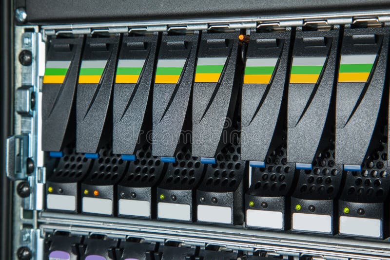
The Storage Tray is a high-density unit designed to host large arrays of NVMe SSDs or disaggregated storage modules for hyperscale and AI data centers. Built for reliability, endurance, and serviceability, the tray supports hot-swap drives, integrated backplane connectivity, and optimized airflow channels that cool densely packed storage devices without thermal throttling. Its architecture ensures consistent I/O performance even under sustained random-access workloads typical of AI pipelines, distributed file systems, and cloud block storage services.
A storage tray prioritizes thermal stability, vibration control, and long-term component lifespan, as SSD performance and endurance degrade when exposed to repeated thermal cycling or elevated controller temperatures. With multiple front-access drive slots, rear power distribution modules, and mid-tray fan channels, it achieves predictable cooling across all bays, even when partially populated. Smart telemetry for temperature, airflow, and SSD health enables proactive monitoring and smooth integration with data center orchestration systems.
Engineered for both new deployments and large-scale retrofits, the storage tray streamlines operational workflows with tool-less service, uniform bay spacing, and mechanical reinforcement to support heavy drive assemblies and large backplane connectors. Its thermal design uses controlled laminar airflow, isolated heat zones, and targeted cooling around SSD controllers, the primary hotspots in flash storage systems.
Storage Tray Components and TIMs Applications
| Component | Typical Power | Thermal Difficulty | Recommended TIM |
|---|---|---|---|
| SSD Controller | 10–15W (hotspot) | High | TGP3500PT / TGP3510PT |
| NAND Flash | Low | Low–Moderate | TGP3000 |
| Drive Heatsink | Varies | Moderate | PTM6880 / TGP3500PT |
| Backplane Connector | Very low | Low | TGF series |
| VRMs (Backplane) | 4–15W | Moderate | TGP6000PT / TGP3500PT |
| BMC / Low Power ICs | <5W | Low | TGP3000 |
| Baseplate / Chassis | — | Moderate | TGP6000 / TGF fillers |
| Retimer / PCIe Switch | 6–12W | Moderate | PTM6600 / TGP3500PT |
Data Center Trays: Compute Trays, Switch Trays, & Storage Trays
In modern data centers, efficient thermal management and optimized performance depend on the specialized roles of compute, switch, and storage trays. Each tray type is engineered for a specific workload—whether executing high-performance AI computations, managing high-bandwidth network traffic, or storing large volumes of data. Understanding their power requirements, heat densities, and critical thermal zones is essential for selecting the right cooling solutions and thermal interface materials (TIMs) to ensure reliable operation and longevity of the hardware. The table below provides a comprehensive overview of these trays, highlighting their primary functions, components, and recommended thermal management strategies.
| Category | Compute Tray | Switch Tray | Storage Tray |
|---|---|---|---|
| Primary Function | High-performance compute for AI, HPC, virtualization | High-bandwidth network switching for cluster interconnect | High-density NVMe storage and data persistence |
| Main Components | CPUs, GPUs/AI accelerators, HBM/DDR5, VRMs, NICs | Switch ASIC, SerDes, optics (OSFP/QSFP-DD), PHYs, VRMs, fan wall | NVMe SSDs, NAND, controllers, backplane, VRMs |
| Typical Power | 250–700W (GPU), 200–350W (CPU) | 200–350W (ASIC), 10–25W per optic, 30–80W VRM | 6–25W per SSD, 10–15W controller |
| Heat Density | Extremely high (AI compute hotspots) | High in ASIC core + localized optics hotspots | Moderate; localized to SSD controllers |
| Key Thermal Challenges | Thin BLT, pump-out, transient loads, high heat flux | Dense ASIC heat, airflow channeling, EMI/SI constraints | Long-term consistency, vibration, hotspot control |
| Cooling Approach | Cold plates, vapor chambers, directed airflow, liquid cooling | High-static-pressure airflow, fin stacks, baffles, redundant fans | Steady airflow, small heatsinks, controlled vibration |
| Critical Hot Zones | GPU die, CPU chiplets, HBM, VRMs | ASIC core, optics bank, VRMs | SSD controller, NAND stack, backplane |
| Preferred TIM Types | High-performance PCM, putty pads, soft gap fillers | High-conductivity PCM + hybrid gap pads | Soft pads, moderate-conductivity gap fillers |
| Solstice TIM Recommendations | PTM7950 / PTM7900 (GPU/CPU), TGP7000/TGP6000 (VRMs), TGP3500 (memory) | PTM7950 / PTM7900 (ASIC), TGP6000PT (optics), TGP3500PT/3510PT (VRMs/PHYs) | TGP3500PT / 3510PT (controllers), PTM6600 (low-power), Gap fillers (backplane) |
Support reliable data server rack deployments.
Solstice Thermal Materials can be purchased through our parent company, Krayden. Contact us to discuss thermal material selection, material compatibility, and long-term reliability considerations for high-density data center and AI cooling systems.