Engineered Solutions for Modern Data Center Infrastructure
Reliable Performance for Next-Generation Compute Workloads
- Home

- Electronics Assembly
- Data Centers
- Direct-to-Chip Liquid Cooling for Data Centers
Direct-to-Chip Liquid Cooling for Data Centers
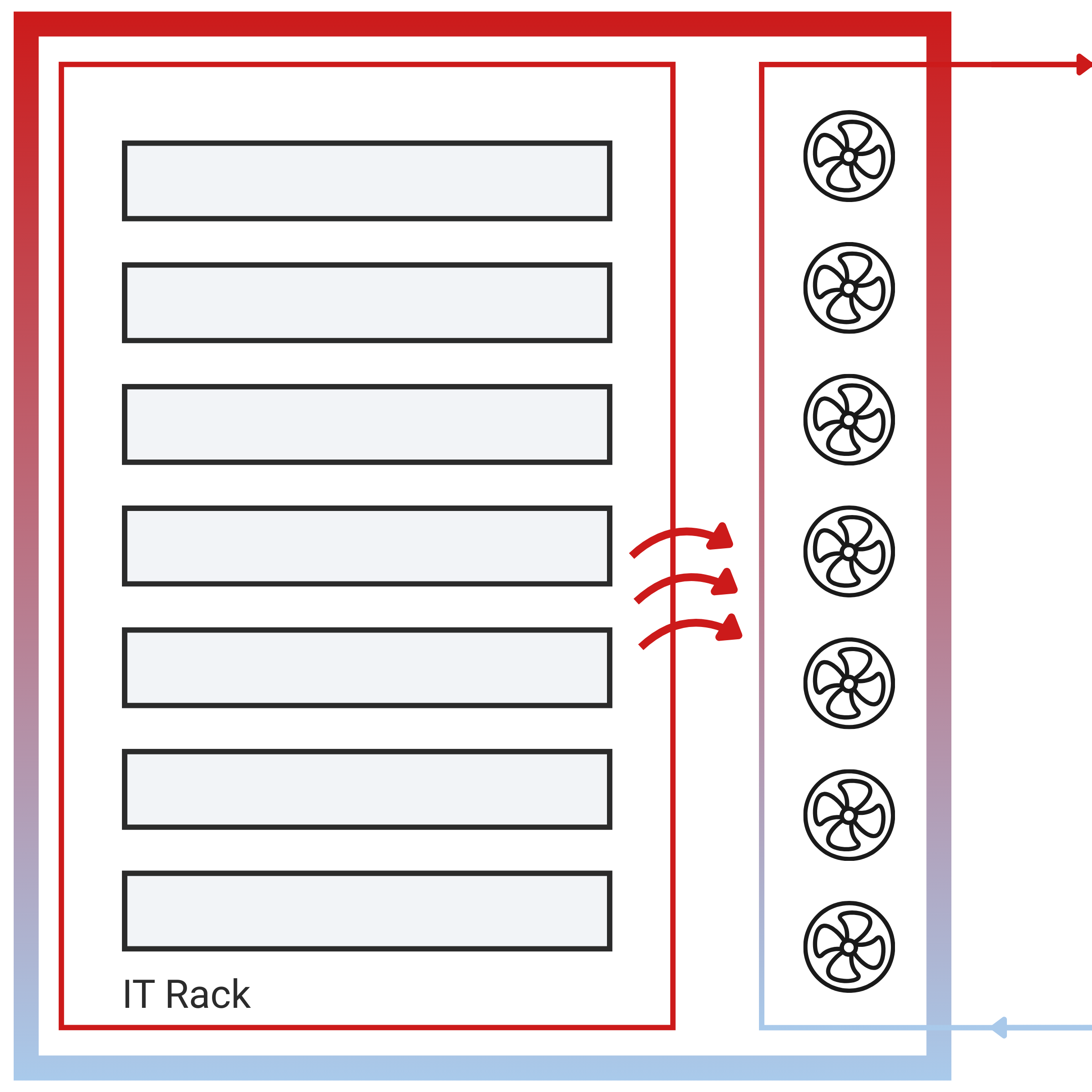
The rapid growth of artificial intelligence (AI), Internet of Things (IoT), and high-performance computing workloads is driving a steady increase in power density in modern data centers. As server performance scales to support these workloads, power consumption rises and heat generation increases at both the rack level and, more critically, at the processor and accelerator level. Today, most data centers rely on air-based datacom equipment cooling systems (DECS) as the primary means of thermal management.
These characteristics define how air cooling is deployed in data centers today, from its widespread adoption to its practical power-density limits.
~80% Market Share
Approximately 70–80% of data centers worldwide continue to rely on air cooling as their primary thermal management approach.
Low Power Density Applications
Air cooling is most commonly used in enterprise, colocation, edge, and legacy data center environments operating at lower rack power densities.
20–35 kW per Rack
Typical operation remains below ~20 kW per rack, with advanced airflow management and containment extending practical limits to ~30–35 kW.
Liquid Cooling Architectures in Modern Data Centers
Today’s high-performance server racks increasingly exceed 20, 30, and even 50 kW. As rack densities rise and heat becomes more concentrated at the processor and accelerator level, the limitations of air-based cooling become more pronounced. In response, data center operators are adopting liquid cooling to manage higher heat flux more efficiently. This shift complements, rather than replaces, air cooling and is commonly implemented through three primary architectures: direct-to-chip cooling, immersion cooling, and rear-door heat exchangers.
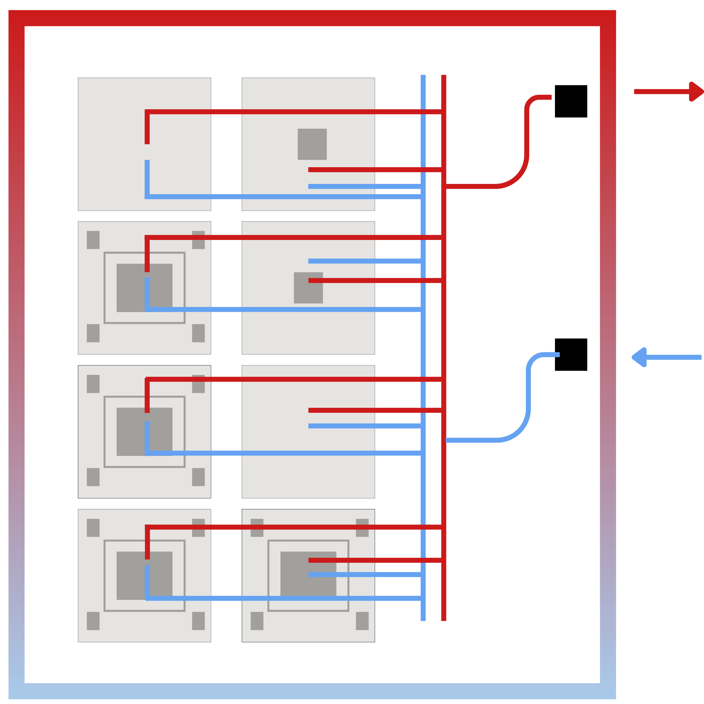
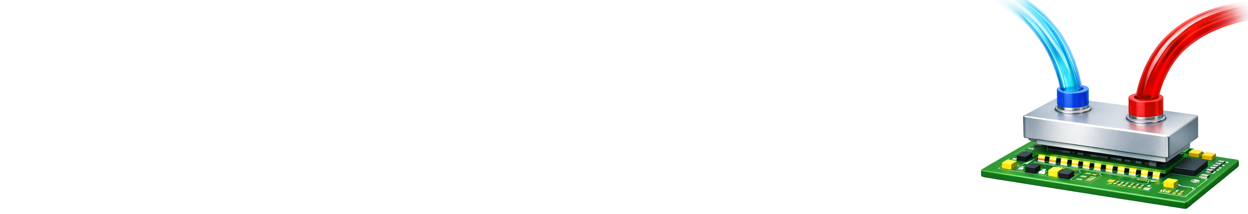
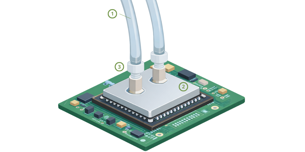
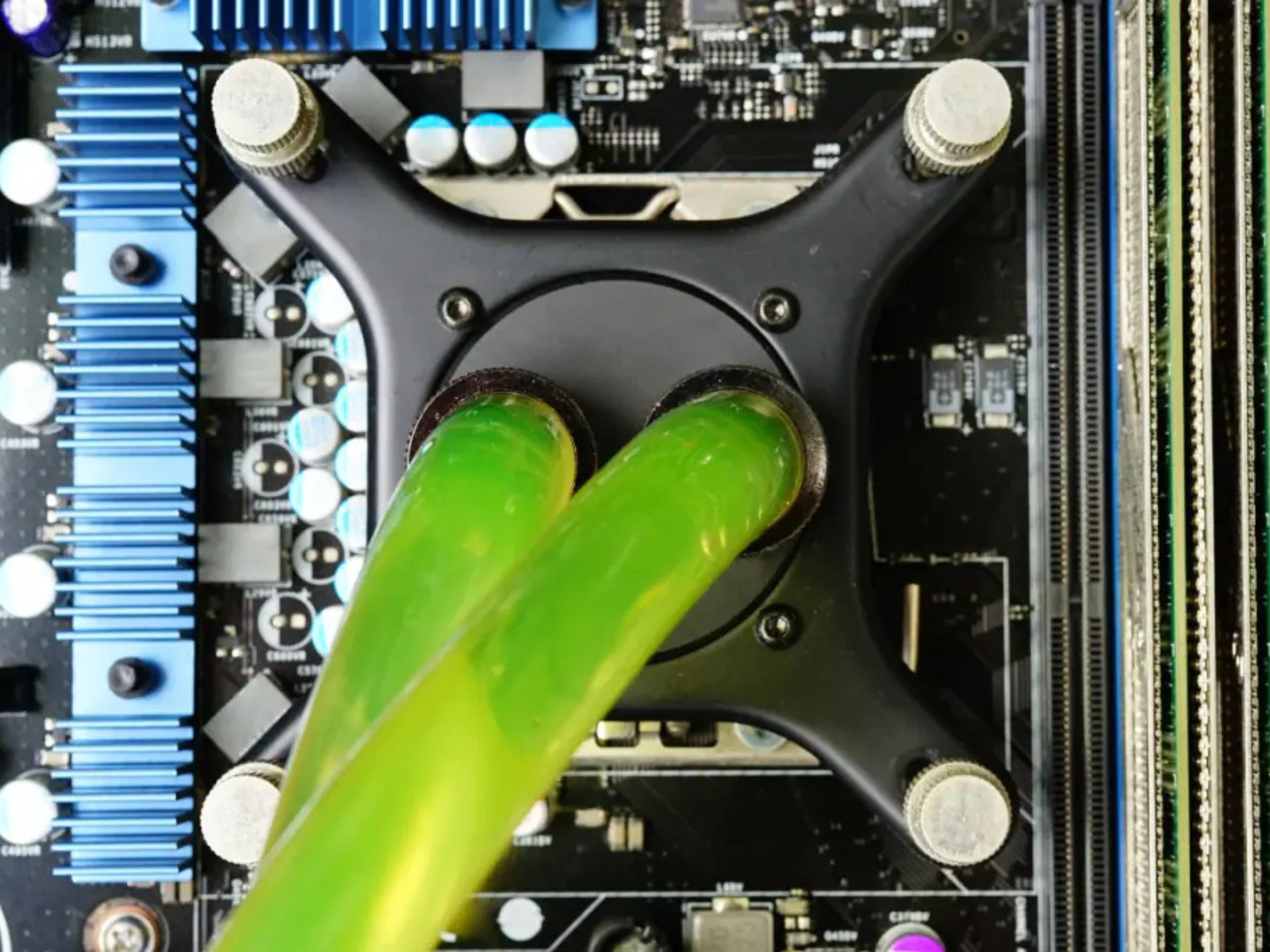
Direct-to-Chip Liquid Cooling
Direct-to-chip cooling removes heat by circulating liquid coolant through cold plates mounted directly on CPUs, GPUs, and accelerators. Heat is extracted at the package level, minimizing thermal resistance and enabling efficient heat removal at the source.
Coolant absorbs heat inside the cold plate and circulates through a closed-loop system before transferring thermal energy to the facility cooling infrastructure.
Lowest thermal resistance, efficient heat extraction at the processor level, and support for very high rack power densities.
Requires liquid distribution infrastructure, coolant management, and careful material compatibility control.
AI training clusters, HPC systems, and accelerator-dense racks where air cooling is no longer sufficient.
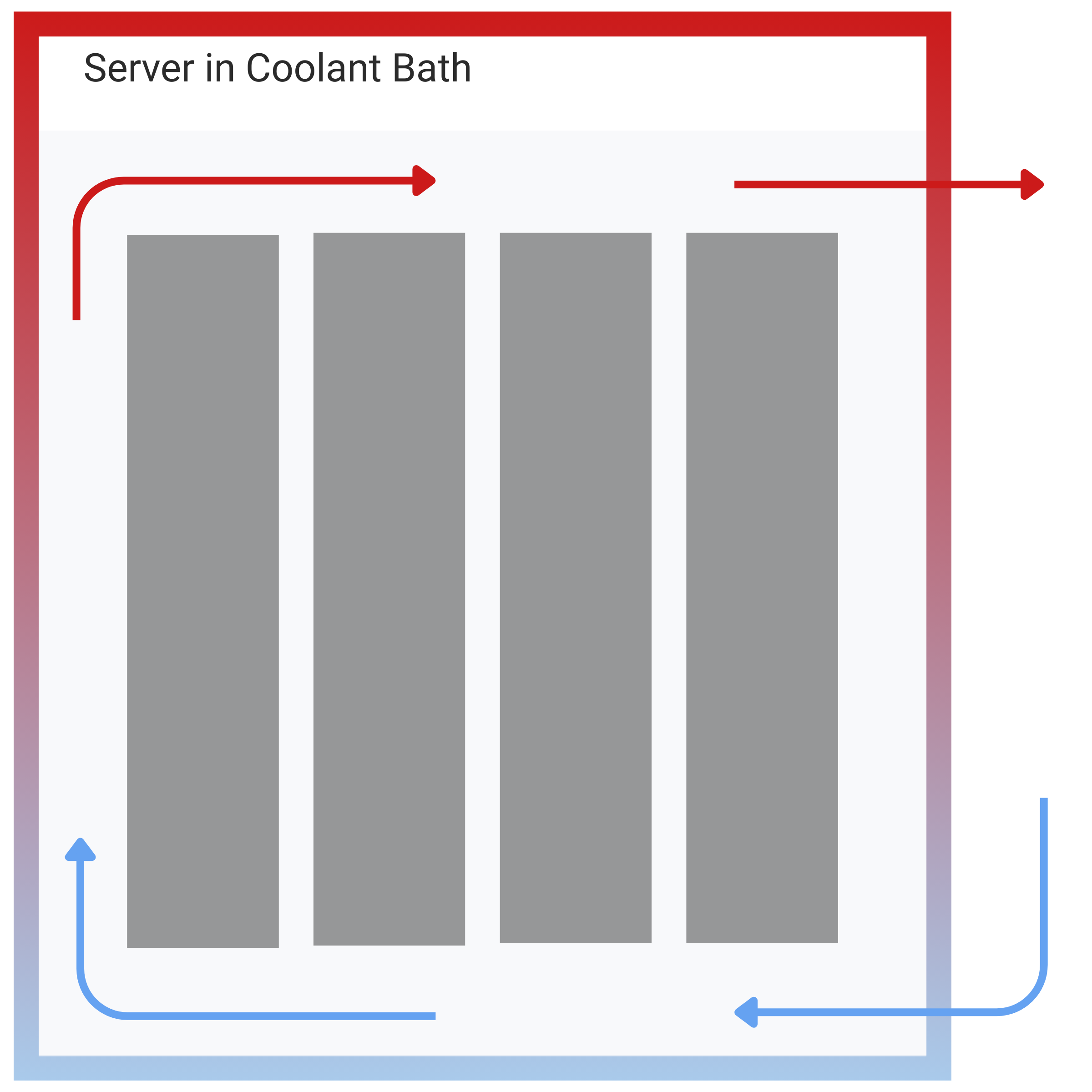
Immersion Cooling
Immersion cooling removes heat by submerging servers or components directly into a dielectric liquid. Heat transfers uniformly from exposed surfaces into the surrounding fluid.
This approach eliminates traditional heat sinks, fans, and internal airflow paths, enabling very high heat flux operation.
Extremely high heat removal capability and simplified thermal paths.
Requires purpose-built hardware, specialized fluids, and changes to service and maintenance workflows.
Ultra-high-density deployments where maximum heat flux outweighs serviceability concerns.
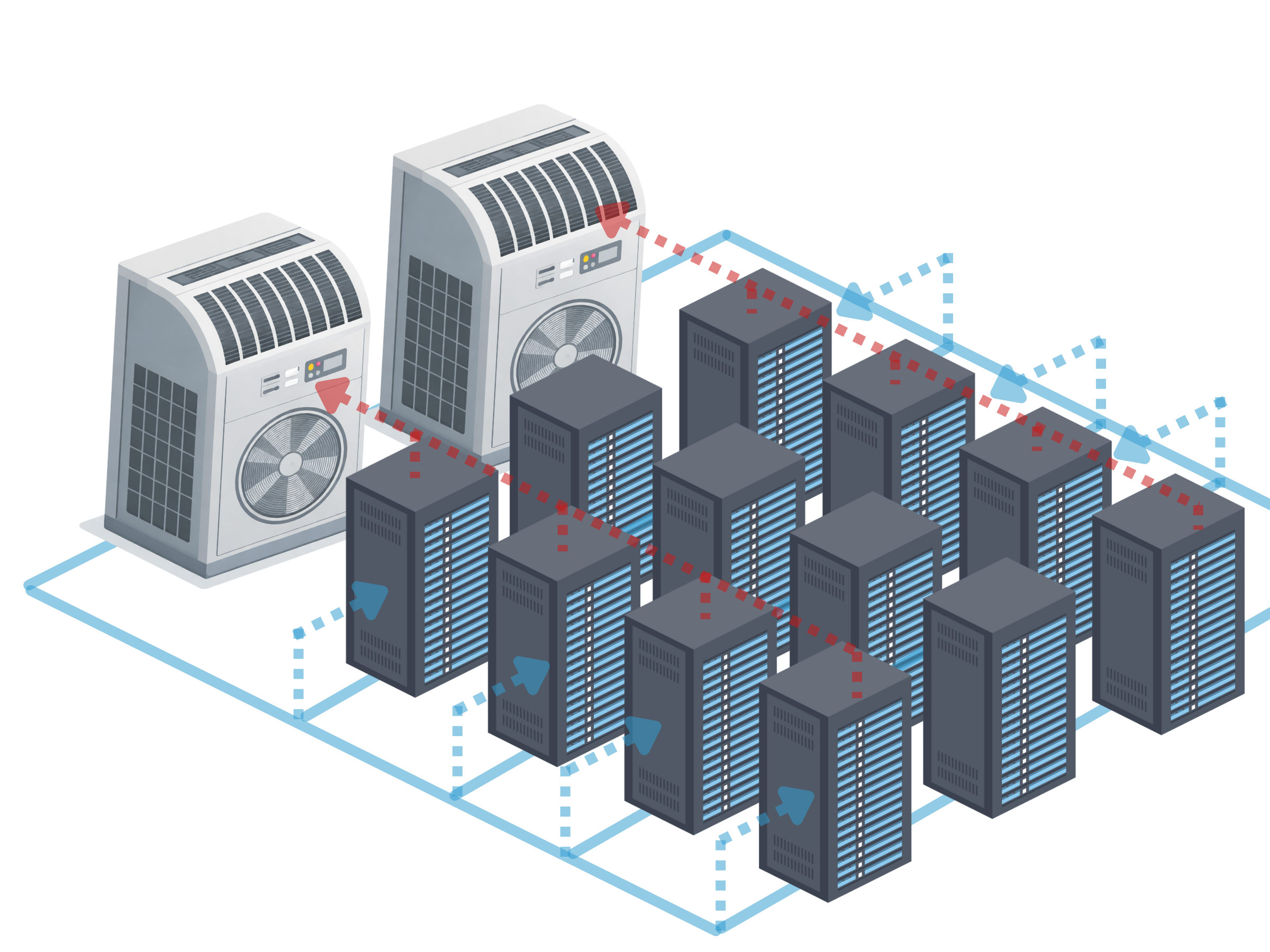
Rear-Door Heat Exchangers (RDHx)
Rear-door heat exchangers remove heat from server exhaust air using liquid-cooled coils mounted on the rear of racks.
Heat transfers from hot air to a liquid loop while servers remain air-cooled internally.
Reduces room heat load and extends the usable range of air-cooled servers.
Does not remove heat at the processor level; chip-level thermal bottlenecks remain.
Retrofit and hybrid air–liquid environments seeking incremental thermal improvements.
How Direct-to-Chip Cooling Works
In a direct-to-chip (D2C) cooling system, heat is removed through a closed-loop liquid path that begins at the processor and ends at the facility cooling system. By extracting heat directly at the chip level, this approach minimizes thermal resistance and enables significantly higher power densities compared to air-based cooling.
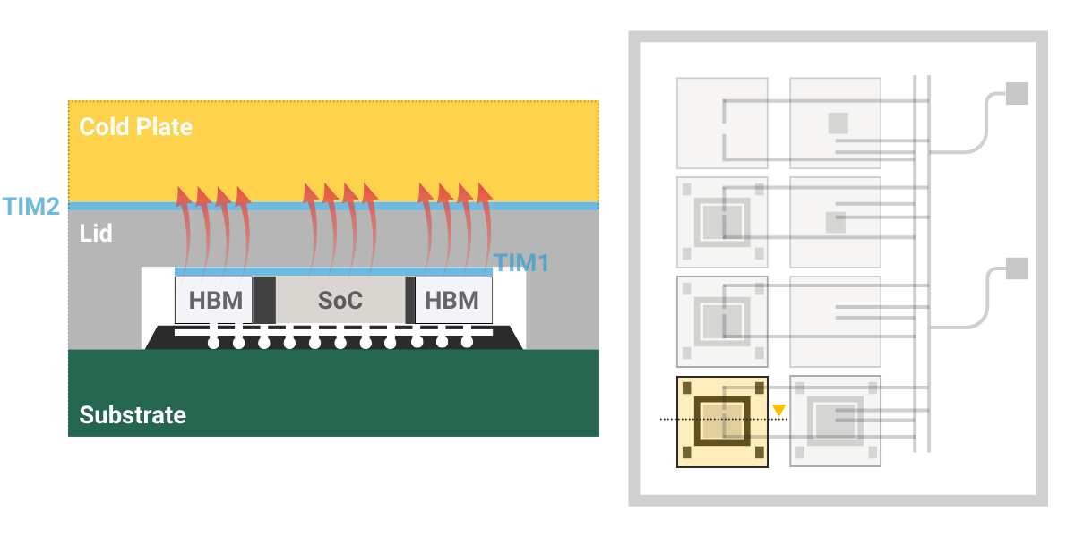
Step 1: Heat Capture at the Processor
Modern CPUs and GPUs generate high heat loads concentrated at the chip surface due to increasing power density. Heat flows from the processor, through a thermal interface material, and into a liquid-cooled cold plate mounted directly on the CPU or GPU.
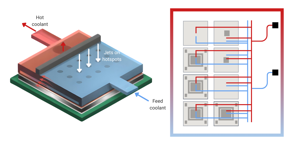
Step 2: Heat Absorption and Transport
Coolant flows through channels inside the cold plate and absorbs heat directly from the processor. Heat is absorbed by the coolant or heat transfer fluid.
In single-phase D2C cooling, the coolant remains in liquid form as it absorbs heat, and its temperature rises.
In two-phase D2C cooling, the coolant absorbs heat by partially changing phase (from liquid to vapor), allowing large amounts of heat to be removed at nearly constant temperature.
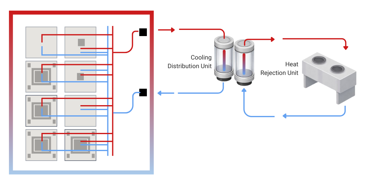
Step 3: Heat Rejection to Facility Cooling
The warmed liquid (or liquid–vapor mixture in two-phase systems) leaves the cold plate and flows through the direct-to-chip cooling loop. Flow is controlled using pumps, manifolds, and valves. Heat carried by the coolant is transferred to the facility cooling system through a heat exchanger.
In single-phase systems, heat is rejected as the liquid is cooled back down. In two-phase systems, vapor condenses back into liquid during heat rejection before being recirculated.
Main Direct-to-Chip Liquid Cooling Components
At the center of direct-to-chip liquid cooling is the heat transfer fluid, or coolant, which governs how effectively heat is managed once it leaves the processor. Beyond enabling heat removal at the cold plate, coolant properties determine thermal performance, materials compatibiity, and long-term reliability across the entire liquid cooling loop.
Key Heat Transfer Fluid Requirements for Direct-to-Chip Cooling
The primary function of a heat transfer fluid is to efficiently remove heat from high-power processors. Key thermal properties include high specific heat capacity to absorb large heat loads, sufficient thermal conductivity to minimize temperature gradients, and stable performance across the operating temperature range of the cooling loop.
These properties directly influence junction temperature, temperature uniformity across cold plates, and overall cooling efficiency at elevated rack power densities.
Viscosity and flow behavior determine how easily the coolant can be circulated through cold plates, manifolds, and heat exchangers. Fluids with excessively high viscosity increase pumping power requirements and system energy consumption.
Optimized flow properties are essential for maintaining uniform coolant distribution, minimizing pressure drop, and enabling scalable cooling architectures as system complexity increases.
Heat transfer fluids must be chemically compatible with a wide range of materials, including metals, elastomers, polymers, seals, and thermal interface materials used in direct-to-chip cooling systems.
Incompatible fluids can lead to corrosion, swelling, leaching, or degradation of system components, ultimately compromising reliability and increasing maintenance requirements.
Direct-to-chip cooling fluids must maintain stable physical and chemical properties over extended operating lifetimes. Resistance to oxidation, thermal degradation, and contamination is critical for long-term system performance.
Stable fluids reduce the risk of fouling, particulate formation, and performance drift, supporting predictable operation and minimizing downtime in mission-critical data center environments.
Heat Transfer Fluids for Direct-to-Chip Cooling
DOWFROST™ LC 25
DOWFROST™ LC 25 is a ready-to-use 25 vol% propylene glycol (PG25) heat transfer fluid for HVAC, data-center cooling loops, process cooling, and direct-to-chip liquid cooling systems. The fluid contains a corrosion-inhibitor package designed to slow glycol oxidation, control pH, and protect common loop materials, including copper, brass, carbon steel, cast iron, and aluminum.
DOWFROST™ LC 25 is formulated using Dow PURAGUARD™ USP/EP-grade propylene glycol (>99.8% purity), reducing contaminants that contribute to odor, discoloration, and accelerated fluid degradation. High base-fluid purity improves chemical stability beyond what inhibitors alone can provide. The fluid is dyed fluorescent yellow-green for leak detection. Gradual color darkening may occur during service and is acceptable if the fluid remains clear and free of suspended solids.
Typical Properties
| Propylene Glycol Concentration | 25 vol% |
| Freezing Point | 14 °F (–10 °C) |
| Boiling Point @ 760 mmHg | 101.4 °C |
| Specific Gravity (25/25 °C) | 1.030–1.036 |
| pH | 8.0–10.5 |
| Reserve Alkalinity | >6.0 mL 0.1 N HCl |
| Thermal Conductivity @ 50 °C | 0.485 W/m·K |
| Specific Heat @ 50 °C | 4.13 kJ/kg·K |
| Viscosity | 2.72 mPa·s @ 20 °C 1.15 mPa·s @ 50 °C |
| Volume Expansion (–10 to 90 °C) | 5.1 % |
| Sulfate Content | <10 ppm |
| Chloride Content | <5 ppm |
| Total Hardness (as CaCO₃) | <20 ppm |
Typical values shown for reference only and should not be used as specifications.
Applications
- Datacom and telecom equipment cooling loops
- Direct-to-chip liquid cooling for high-performance processors and accelerators
- Data center thermal management and rack-level liquid cooling systems
- HVAC and process cooling systems requiring long-term fluid stability
- Suitable for systems where fluid cleanliness, material compatibility, and long-term corrosion control are critical
Corrosion Performance of DOWFROST™ LC 25
Long-term reliability of direct-to-chip liquid cooling systems depends on strict control of corrosion across all wetted materials. Comparative corrosion testing demonstrates that DOWFROST™ LC 25 delivers excellent corrosion protection across all metals tested, achieving orders-of-magnitude lower corrosion rates than water and uninhibited propylene glycol.
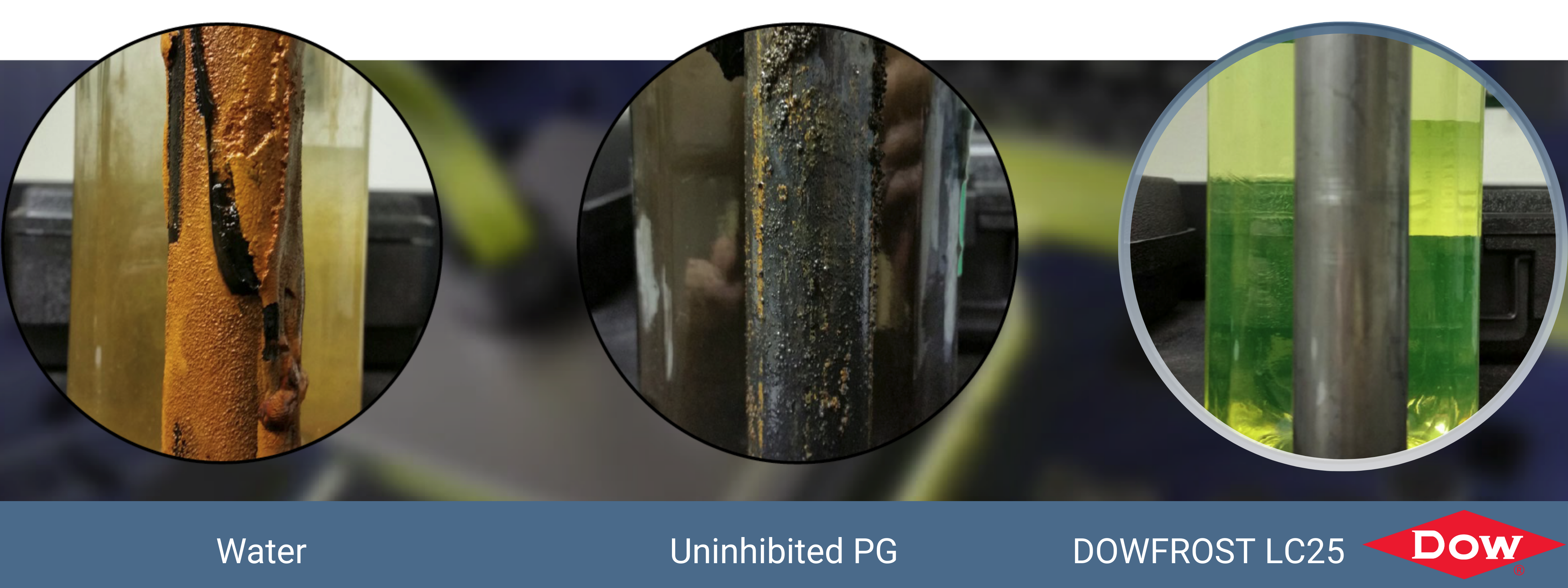
Visual comparison of metal corrosion after exposure to water, uninhibited propylene glycol, and DOWFROST LC 25
Key Findings
- Extremely low corrosion rates across copper, steel, iron, brass, solder, and aluminum
- Orders-of-magnitude improvement compared to water and uninhibited propylene glycol
- All measured values fall well below commonly accepted corrosion thresholds
- Suitable for mixed-metal liquid cooling loops in high-density data center environments
| Metal | Water (mpy) | Uninhibited PG (mpy) | DOWFROST™ LC 25 (mpy) |
|---|---|---|---|
| Copper | 0.08 | 0.16 | 0.03 |
| Solder | 3.14 | 34.70 | 0.04 |
| Brass | 0.23 | 0.20 | 0.07 |
| Mild Steel | 9.69 | 9.80 | 0.02 |
| Cast Iron | 21.20 | 16.20 | 0.02 |
| Aluminum | 13.20 | 1.80 | 0.31 |
Corrosion performance evaluated using ASTM D1384 testing at 190 °F (88 °C) for two weeks with constant air bubbling. Glycol solutions were prepared at 30 vol%. Corrosion rates are reported as mils penetration per year (mpy). Corrosion rates above 0.5 mpy (2.5 mpy for aluminum) generally indicate insufficient corrosion protection.
For detailed specifications, material properties, and application guidance relevant to direct-to-chip liquid cooling:
Frequently Asked Questions About DOWFROST™ LC 25
▶ Is DOWFROST™ LC 25 compatible with elastomers and plastics used in liquid cooling systems?
DOWFROST™ LC 25 is formulated to maintain chemical compatibility with a wide range of elastomers and plastics commonly used in liquid cooling systems operating at bulk fluid temperatures up to 90 °C (194 °F). Compatibility depends on both material type and allowable service temperature, which can vary significantly between different formulations of the same polymer or elastomer.
Materials such as PTFE and FEP exhibit excellent compatibility at elevated temperatures, while EPDM, polyethylene (PE), polypropylene (PP), and polysulfone-based polymers (PSU, PPSU) are generally suitable for operation up to approximately 75 °C.
Some elastomers and plastics, including NBR, silicone, polyamide (PA), polyoxymethylene (POM), and certain fluoroelastomers (FKM), may have lower recommended temperature limits or reduced long-term stability when exposed to propylene glycol–based fluids.
▶ Can DOWFROST™ LC 25 heat transfer fluid be diluted?
DOWFROST™ LC 25 is a ready-to-use heat transfer fluid and should not be diluted. It is formulated with the correct concentration of corrosion inhibitors to protect datacom equipment cooling systems (DECS) and other liquid cooling loops. Dilution lowers inhibitor effectiveness and can increase the risk of corrosion, scaling, and biological fouling.
If dilution is unavoidable, only purified water—distilled, deionized (DI), or reverse osmosis (RO)— should be used. Untreated or mineral-rich water can introduce contaminants that degrade system reliability.
Minimum water quality limits for any unavoidable dilution:
| Total Chlorides (as Cl⁻) | < 25 mg/L |
| Total Sulfates (as SO₄²⁻) | < 25 mg/L |
| Total Hardness (as CaCO₃) | < 50 mg/L |
| Total Iron (as Fe) | < 1 mg/L |
| Electrical Conductivity | < 50 µmhos/cm |
| pH | 5 < pH < 9 |
▶ Why does DOWFROST™ LC 25 have higher electrical conductivity than purified water, and is it a concern?
DOWFROST™ LC 25 contains corrosion inhibitors, pH buffers, and stabilizing additives that are intentionally added to protect metals and maintain long-term fluid performance. These additives increase ionic content, resulting in electrical conductivity values typically above 2,000 µmhos/cm. This behavior is normal for a fully formulated heat transfer fluid.
The higher conductivity is not a concern because DOWFROST™ LC 25 is used in closed-loop liquid cooling systems, where the fluid is fully contained and isolated from electronic circuits. Conductivity reflects the chemistry required for corrosion control and system reliability, not electrical risk.
Further Reading on Direct-to-Chip Cooling

Support reliable direct-to-chip liquid cooling deployments.
DOWFROST™ LC 25 can be purchased through our parent company, Krayden. Contact us to discuss heat transfer fluid selection, material compatibility, and long-term reliability considerations for high-density data center and AI cooling systems.