Light Emitting Diodes
Lightning, Biological and Indicators
- Home

- Semiconductors
- Light Emitting Diodes
- Optocoupler
Optocoupler
Optocouplers for Industrial Control, Metering, and Power Conversion
Optocouplers (photocouplers, opto-isolators) transfer signals across an optical path while maintaining galvanic isolation between an input control domain and an output domain that may be higher voltage, noisier, or on a different ground. They are used to protect low-voltage electronics from transients and ground shifts, and to improve noise immunity between subsystems.
CAPLINQ supports optocoupler package reliability by supplying white and black epoxy molding compounds (EMCs) designed for optical efficiency, molding robustness, and moisture resistance.
Why Isolation Reliability Shifts From Device Ratings to Package Execution
As switching edges sharpen and noise margins tighten in power supplies, motor drives, and metering front ends, isolation performance increasingly fails at interfaces, not inside the silicon. The limiting factor often shifts from basic signal transfer to insulation stability after humidity bias, thermal cycling, and assembly-driven defects such as voids or interfacial delamination.
Isolation capability must be interpreted by rating type (withstand test voltage, working voltage, surge), then verified at the package level after realistic preconditioning. In practice, molding integrity, ionic cleanliness, and adhesion to leadframe and internal surfaces determine whether isolation margin remains stable over life.
Typical packages, output devices, and qualification gates
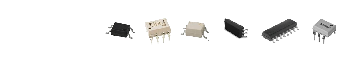
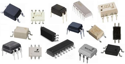
Optocouplers integrate an infrared LED and a photosensitive receiver inside one package to transfer information across a dielectric isolation barrier. Isolation is a system outcome: it depends on the rating definition used by the device supplier (withstand, working voltage, surge) and on package geometry (creepage and clearance), then it must remain stable after assembly and environmental stress.
Package: SOP4, SOP5, SOP8, SOP16, DIP4, DIP6, DIP8, etc.
Output device families: phototransistor, photodarlington, photoTRIAC / photoSCR, gate-drive oriented optocouplers.
- JEDEC MSL preconditioning (for example MSL3 to MSL1), reflow at 260°C
- High-temperature storage: 150°C, 1000 hours
- Temperature cycling: -55 to 125°C, 1000 cycles
- uHAST: 130°C, 85%RH, 168 hours
- Temperature humidity bias (THB): 85°C, 85%RH with bias, 1000 hours
Note: final qualification depends on isolation class, package geometry, PCB spacing, and end-use environment. Add or tighten gates when the application includes high dV/dt switching, condensation risk, or higher insulation class requirements.
Applications of Optocouplers
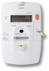
Optocouplers are used when a control or measurement circuit must interface with a higher-voltage or noisier domain without a direct electrical connection, or when grounds can shift between subsystems. They support isolation, noise immunity, and fault protection in mixed-voltage systems.
In real assemblies, isolation performance is limited by package execution, not only by device ratings. Voids, interfacial delamination, cracking, and ionic contamination can reduce insulation resistance after MSL preconditioning, humidity bias, and thermal cycling.
- Isolation definition: withstand, working voltage, surge, creepage and clearance
- Noise environment: common-mode transients and ground shift
- Transfer margin: CTR or transfer gain across temperature and end-of-life
- Package reliability: MSL, THB, uHAST, thermal cycling, void and delamination control

Key EMC Requirements for Optocoupler Encapsulation
Property: insulation resistance under bias, reflectance or transmittance (defined wavelength and thickness), dielectric withstand at real thickness
Controls: isolation margin and optical transfer stability
Failure mode avoided: leakage increase, isolation drift, optical loss driven CTR drop
Validate: THB, withstand test per plan, optical retention after heat aging
Property: spiral flow, gel time, viscosity profile, filler PSD control
Controls: fill completeness, void rate, wire sweep, flash and bleed
Failure mode avoided: void-driven leakage and delamination-driven moisture paths
Validate: DOE on fill, CSAM or X-ray, wire sweep inspection
Property: adhesion after MSL, ionic cleanliness, silicone interface compatibility (if present)
Controls: interfacial stability and moisture ingress resistance
Failure mode avoided: delamination, surface leakage, corrosion-assisted drift
Validate: CSAM after reflow and humidity, red ink where applicable
Property: reflectance retention after heat exposure, moisture resistance, crack resistance under cycling
Controls: lifetime transfer margin and insulation stability
Failure mode avoided: CTR drift beyond design margin, leakage drift under humidity bias
Validate: HTS, TC, uHAST, THB, reflectance retention under defined setup
- Optical: reflectance or transmittance at target wavelength (example: 800 nm, 940 nm), measured at defined thickness
- Electrical: insulation resistance and leakage under bias after MSL and THB
- Integrity: void rate, delamination area, wire sweep, flash and bleed
- Cleanliness: ionic residues, mold release control, time-to-mold after surface prep
Details placeholder: [Insert your qualification gates and acceptance criteria for voids, delamination, reflectance retention, and leakage.]
Encapsulation Architectures for Optocouplers
Optocouplers are commonly molded with EMC to protect the optical die, wires, and leadframe while maintaining stable insulation and optical performance. Two approaches are common depending on optical geometry and external light sensitivity.
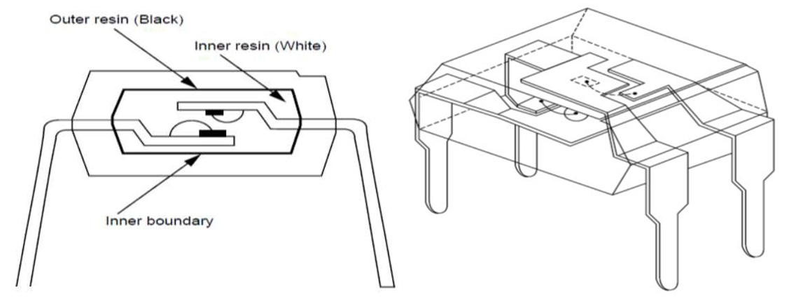
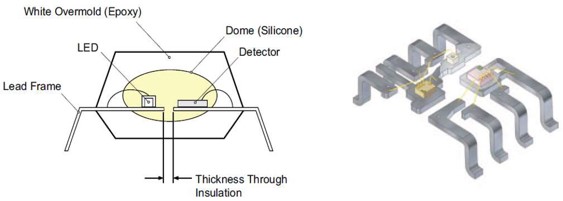
At the center of optocoupler package reliability is the molded isolation barrier and optical cavity, which govern electrical isolation, optical efficiency, and stability under moisture exposure and thermal cycling.
CAPLINQ EMC Solutions for Optocoupler Encapsulation
Product selection should follow the constraint first. White EMCs are selected for optical efficiency and reflectance retention, plus molding stability and moisture robustness. Black EMCs are selected for light blocking, moisture resistance, and stable adhesion to reduce delamination-driven leakage or isolation drift.
Contact us to confirm the right product for your package and application.
| Constraint | Material / process levers | Recommended CAPLINQ grades |
|---|---|---|
| Optical coupling loss | High reflectance or controlled transmittance at wavelength, pigment stability | OPTOLINQ WMC-G261, OPTOLINQ WMC-G279 |
| Yellowing and reflectance decay | Anti-yellowing formulation, oxidation resistance, controlled cure | OPTOLINQ WMC-G261, OPTOLINQ WMC-G279 |
| Moisture driven leakage | Moisture resistance, low ionic contamination, void control | LINQSOL EMC-G274, LINQSOL EMC-G241 |
| Interfacial delamination | Adhesion after MSL, surface cleanliness control, balanced stress | LINQSOL EMC-G274, LINQSOL EMC-G241 |
| Flash, bleed, and wire sweep | Stable flow window, controlled gel time, filler PSD control | WMC-G261 / WMC-G279, EMC-G274 / EMC-G241 |
White EMC for inner cavity and single-mold white designs (priority)
- OPTOLINQ WMC-G261 | [Go to Product Page↗]
- OPTOLINQ WMC-G279 | [Go to Product Page↗]
- HYSOL GR17 | [Go to Product Page↗]
Black EMC for external mold in double-mold designs (priority)
- LINQSOL EMC-G274 | [Go to Product Page↗]
- LINQSOL EMC-G241 | [Go to Product Page↗]
- HYSOL GR300S | [Go to Product Page↗]
Territory disclaimer: The GT-W170 Series is available for non-Asia territories only. For Asia programs, prioritize OPTOLINQ WMC-G261, OPTOLINQ WMC-G279, LINQSOL EMC-G274, and LINQSOL EMC-G241, and contact CAPLINQ for grade selection support based on package type and qualification requirements.
Reflectance Retention and Yellowing Behavior
The plots and images below illustrate how reflectance retention and yellowing can be evaluated under a defined heat oxidation exposure. Use this as a reference method. Equivalent validation should be performed on the program-grade material using the correct wavelength, thickness, and aging condition.
Details placeholder: [Insert thickness, measurement instrument, wavelength range, and acceptance criteria.]
GT-W170 Reliability Test Results (Non-Asia territory reference)
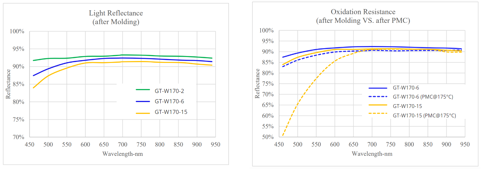
Reflectance behavior under the stated oxidation exposure
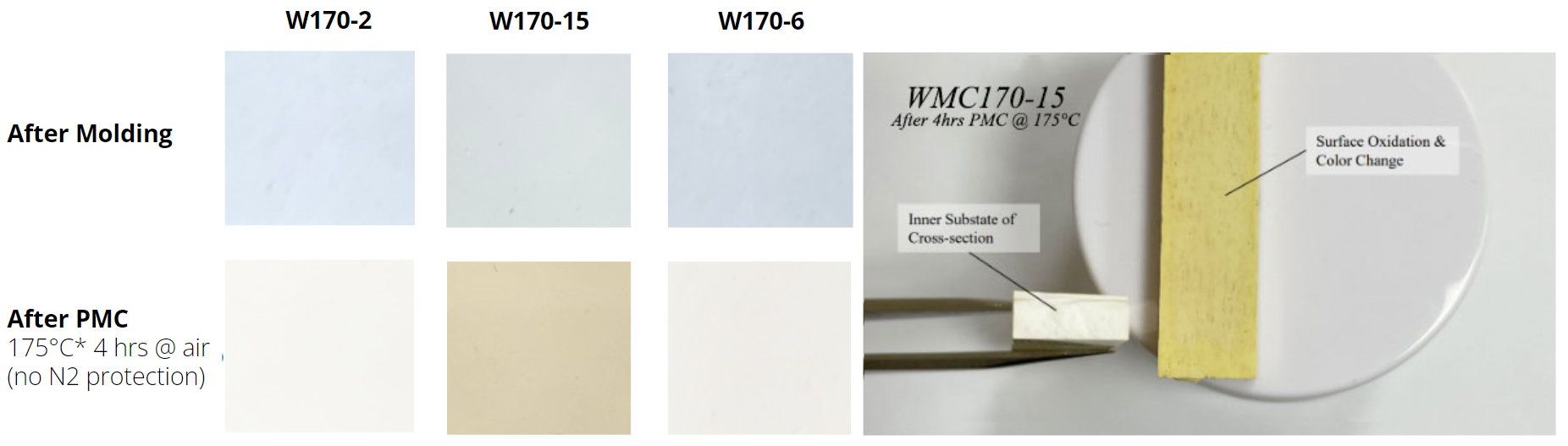
Key Findings
- Anti-yellowing ranking: W170-2 > W170-6 > W170-15
- At wavelengths above 700 nm, minimal reflectance decrease is observed under the stated condition.
- At wavelengths below 650 nm, W170-15 shows reflectance drop consistent with visible yellowing sensitivity.
Test condition shown: [Insert the full condition statement as used in your internal dataset.]
De-risk optocoupler molding and qualification.
Contact us with your package type, optical wavelength (for example 850 nm or 940 nm), isolation rating definition required by your program, and your qualification targets.