- Home

- Products
- Electrochemical Materials
- Ion Exchange Membranes & Polymers
- AEMION+™-AF3N-HWC9-75
AEMION+™-AF3N-HWC9-75

- Recommended for AEM Water Electrolysis, Acid Recovery, and Salt Splitting
- Single-Step Activation for Reduced Membrane Processing Time
- 75-µm thick membrane with woven PEEK reinforcement
Product Description
AEMION+™-AF3N-HWC9-75 is an advanced polyimidazolium-based anion exchange membrane designed for AEM water electrolysis. It is the updated version of AEMION+™-AF3-HWC9-70, built on the same composite membrane platform with no changes to the membrane components or stability.
AEMION+™ membranes are known for their low ionic resistance, high electrical resistance, and stability across the full pH range (0–14). Their hydrocarbon polymer structure enables operation in harsh electrochemical environments while maintaining good mechanical strength and durability. The membranes exhibit strong chemical stability in both acidic and alkaline solutions. They are compatible with KOH electrolytes typically used in AEM electrolysis, operating in concentrations of 0.5–2 M at temperatures up to 80 °C.
AEMION+™-AF3N-HWC9-75 maintains the same membrane resistance and electrolyzer performance as AF3-HWC9-70, with testing showing equivalent or improved results. The main difference is the counterion form. AF3-HWC9-70 is supplied in halide form and requires a two-step activation process. AF3N-HWC9-75 is produced in nitrate form, enabling a single-step activation process.
This simplified activation reduces processing time and material consumption during membrane preparation. The ion exchange can also be performed directly in the stack, enabling dry stack assembly. Combined with the membrane's low swelling, this makes AF3N-HWC9-75 suitable for dry cathode operation and automated assembly lines.
Key Features:
- Single-step activation
- Excellent chemical stability across the full pH range (0–14)
- Low ionic resistance
- High electrical resistance:
- Excellent mechanical integrity
- Minimal swelling
Highly Recommended for:
- AEM water electrolyzers
- Dry cathode electrolyzer designs
- Automated stack assembly lines
- Acid recovery systems
- Salt splitting processes (membrane-based separation processes)
- Electrodialysis or electrochemical concentration of acid
Technical Specifications
| General Properties | |||||
| Total Thickness Total Thickness Total thickness is taking into account all the films, coatings, adhesives, release liners and special layers and is the maximum thickness of a film or tape. | 70–75 μm | ||||
| Thermal Properties | |||||
| Glass Transition Temperature (Tg) Glass Transition Temperature (Tg) The glass transition temperature for organic adhesives is a temperature region where the polymers change from glassy and brittle to soft and rubbery. Increasing the temperature further continues the softening process as the viscosity drops too. Temperatures between the glass transition temperature and below the decomposition point of the adhesive are the best region for bonding. The glass-transition temperature Tg of a material characterizes the range of temperatures over which this glass transition occurs. | >300 °C | ||||
| Mechanical Properties | |||||
| Elongation Elongation Elongation is the process of lengthening something. It is a percentage that measures the initial, unstressed, length compared to the length of the material right before it breaks. It is commonly referred to as Ultimate Elongation or Tensile Elongation at break. | >15 % | ||||
| |||||
| Physical Properties | |||||
| Young's modulus | 600–850 MPa | ||||
| Hydrolytic Properties | |||||
| Linear Expansion | 3 (22 °C) % | ||||
| Water Uptake | 15 (22 °C) % | ||||
| Z-Expansion | 5 (22 °C) % | ||||
| Electrochemical Properties | |||||
| Thru Plane Cl- Conductivity | >5 | ||||
Additional Information
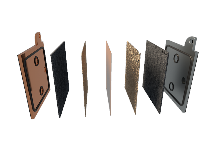
AEMION+® Enables Large-Scale Commercial Development of Water Electrolyzers
Alkaline water electrolysis (AWE) uses a liquid KOH/NaOH electrolyte between electrodes separated by a porous diaphragm. It benefits from low-cost catalysts but suffers from higher internal resistance and typically lower current densities.
Proton exchange membrane water electrolysis (PEMWE) is compact and efficient due to high H+ conductivity, but the acidic environment drives reliance on PGM catalysts—raising CAPEX and OPEX.
This motivates a technology that blends AWE’s inexpensive catalysts with PEMWE’s compact zero-gap design: alkaline anion exchange membrane water electrolysis (AEMWE/AAEMWE). Using an anion exchange membrane enables low-cost catalysts while maintaining a compact architecture. At current scales, AWE and PEMWE CAPEX exceed DOE targets; AEMWE offers a pathway to lower CAPEX and competitive green hydrogen. Developing high-performance, stable AEMs is central to this transition.
| Description | AWE | PEMWE | AEMWE |
|---|---|---|---|
| Technology readiness | ✓ | ✓ | ✕ |
| Non-PGM loading | ✓ | ✕ | ✓ |
| Long-term stability | ✓ | – | ✕ |
| MW scale | ✓ | ✓ | ✕ |
| Compact design | ✕ | ✓ | ✓ |
| Current density | ✕ | ✓ | ✓ |
| Cost effective | – | ✕ | ✓ |
| Operating pressure | ✕ | ✓ | ✓ |
| Non-corrosive environment | ✕ | ✕ | ✓ |
At 1 MW, AWE ($1279/kW) and PEMWE ($1168/kW) are similar, while AEMWE with AEMION+® is lower at $931/kW and $926/kW (without/with PGM). At 5 MW, all costs drop but AEMWE remains lowest ($444–459/kW). The pathway to low-cost, sustainable electrolysis is enabled by continued AEMWE advances. | 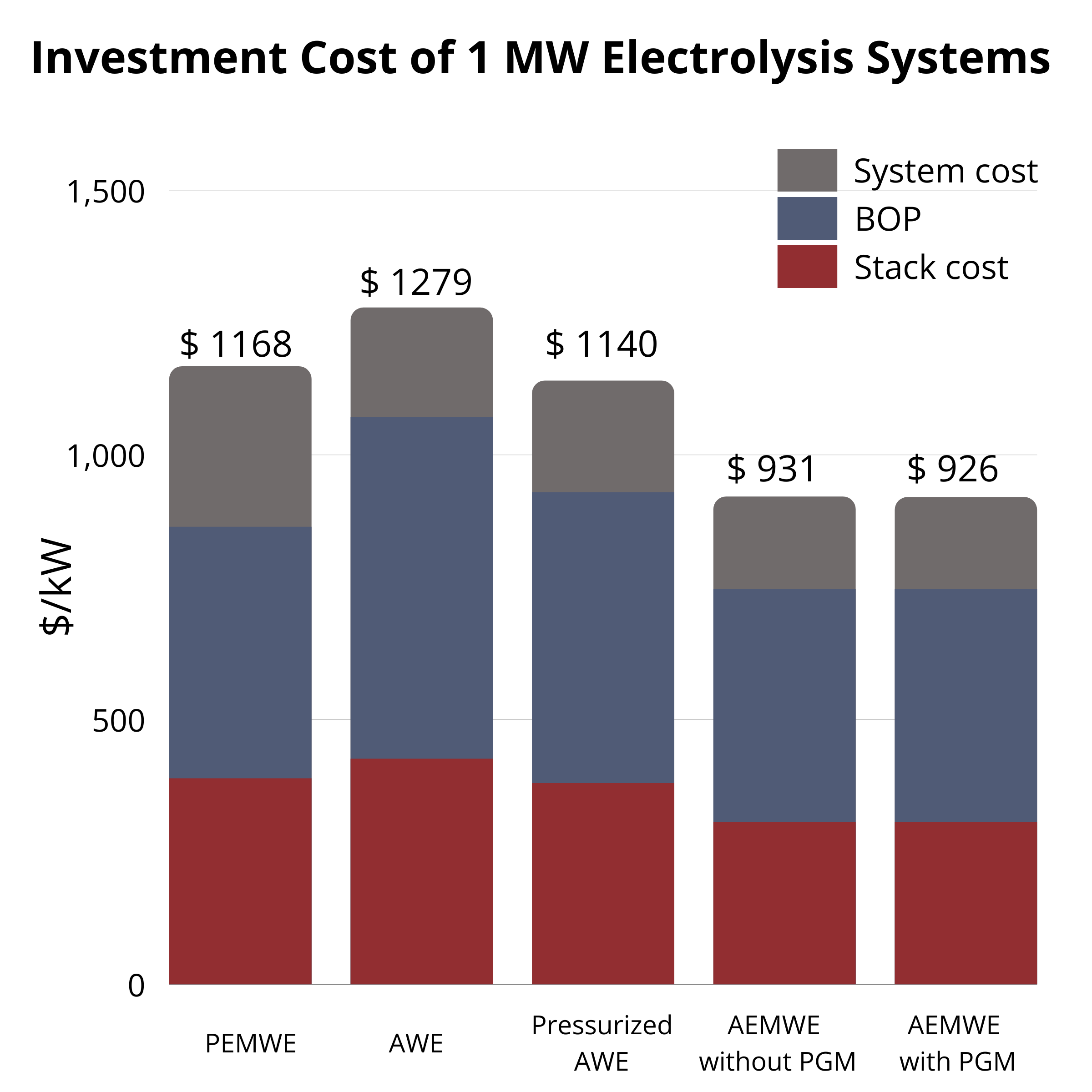 CAPEX at 5 MW | 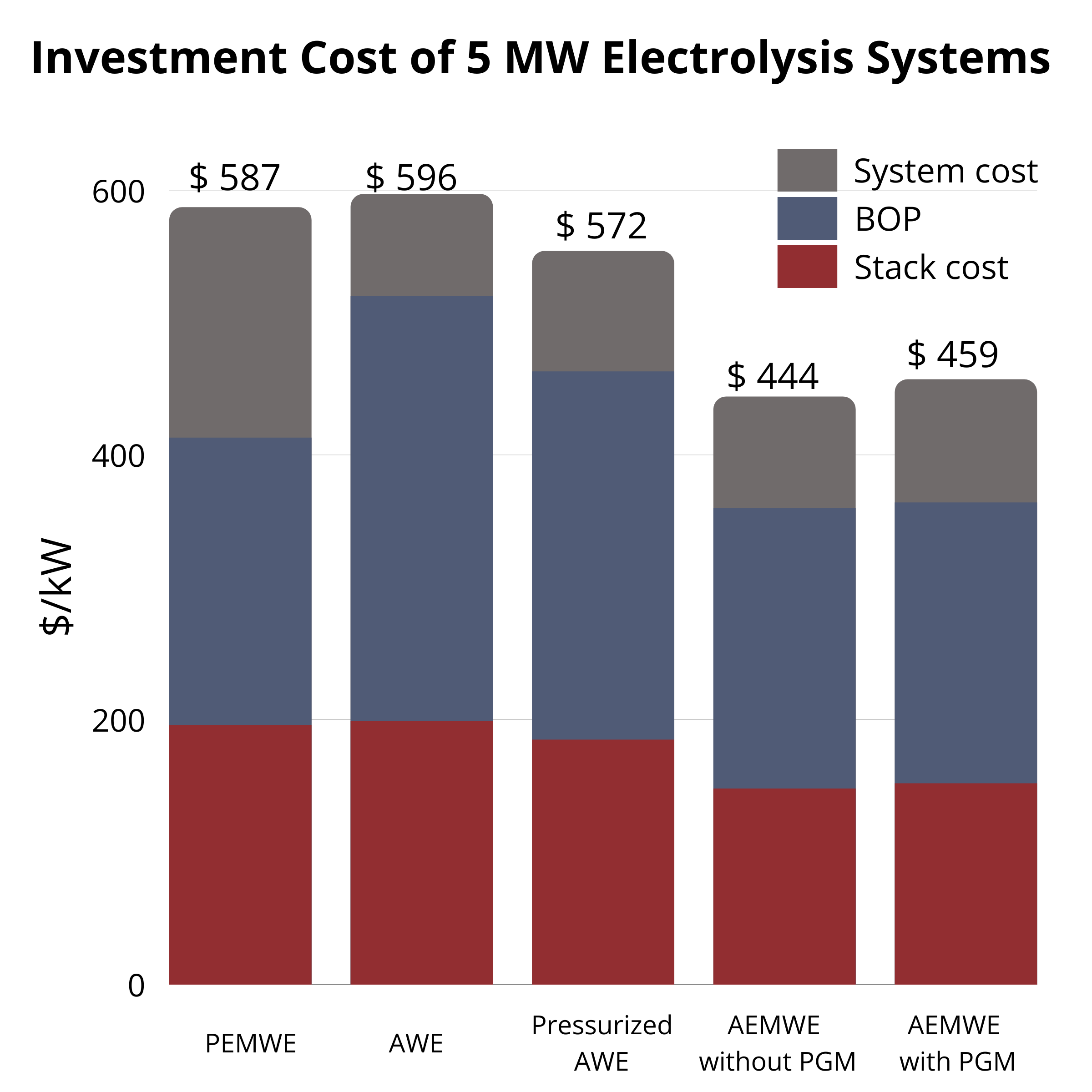 CAPEX at 1 MW |
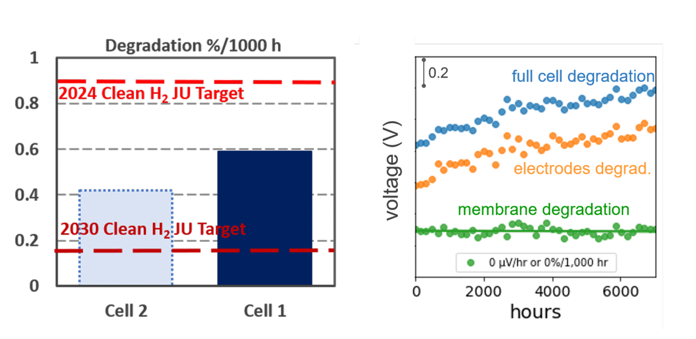
Zero Degradation Found in Latest Test of Aemion+® Alkaline Membrane
Background. A 50 cm2 cell using Aemion+® membranes and long-life alkaline electrodes has been on-test for 2500 h at the 2024 EU target current density (0.6 A cm−2), building on >7500 h prior tests with <0.6%/1000 h post break-in system degradation and <0.05%/1000 h measurable membrane degradation.
Results. Cells showed no detectable membrane degradation (<0.05%), with total system degradation <0.4%/1000 h—surpassing the EU Clean Hydrogen JU 2024 target of 0.9%/1000 h. Most losses came from electrodes/porous metal transport elements; removing the porous metal improved outcomes. Ionomr continues optimization with NREL under Shell GCxN. NREL reports Ionomr MEAs >1 A cm−2 at 2 V in hydroxide electrolyte without iridium and stable >500 h. See the latest press release.
Key Specifications of AF3N-HWC9-75-X
| Membrane Type | Typical Thickness (µm) | IEC1 (meq/g) | Reinforcement |
|---|---|---|---|
| AF3N-HWC9-75-X | 75 ± 5 | 2.1 – 2.6 | Woven PEEK |
| Property | MD / Value | TD | Test Method |
|---|---|---|---|
| Physical Properties2 | |||
| Tensile Strength (MPa) | 50–60 | 50–60 | ASTM 638 |
| Young’s Modulus (MPa) | 600–900 | 600–900 | ASTM 638 |
| Elongation at Break (%) | > 20 | > 20 | ASTM 638 |
| Hydrolytic Properties | |||
| Water Uptake (%) — 22 °C | < 20 | ASTM D570 | |
| Water Uptake (%) — 80 °C | < 20 | ||
| Linear Expansion (%) — 22 °C | < 3 | ASTM D570 | |
| Linear Expansion (%) — 80 °C | < 3 | ||
| Z-Expansion (%) — 22 °C | < 15 | ASTM D570 | |
| Z-Expansion (%) — 80 °C | < 15 | ||
| Electrochemical Properties | |||
| Through-plane Cl− Conductivity (mS·cm−1) | > 4 | Internal4 | |
| Hydrogen Permeability (N μL·cm−2·min−1·bar−1) | < 3.6 | Internal5 | |
| Chemical Stability | |||
| Recommended Operating Condition | 1 M KOH, 70 °C | Internal6 | |
| Other Properties | |||
| Maximum Processing Temperature (°C) | 180 | Internal7 | |
| Polymer Tg (°C) | > 300 | ASTM E1131 / ISO 11358 | |
| Counter-ions as Produced | NO3− (nitrate) | — | |
- Polymer IEC in the hydroxide (OH−) counter-ion form.
- Measured at 22 °C fully hydrated.
- Measured in native ionic form.
- Treated in 1 M NaCl for 24 hours, then in DI H2O for 6 hours to ensure complete hydration. Testing conducted fully submerged in DI H2O at room temperature.
- Not a standard test. Hydrogen permeability is measured electrochemically in internal testing condition for reference only and is not necessarily representative of customer conditions. It is recommended to verify permeability in individual systems once received.
- Measured ex-situ by determining steady-state mechanical strength, conductivity, and IEC at specified temperature and regularly exchanged KOH electrolyte.
- Determined by thermogravimetric analysis (TGA) at 2 °C/min in as-produced form. Polymer can be rendered stable above 200 °C.
Handling, Storage and Safety
Handling
- Store, handle, and process membranes in a clean, dust-free environment.
- Use only new and sharp blades when cutting membranes to ensure clean edges.
- Wear gloves during handling to prevent contamination.
- Handle membranes carefully and avoid puncturing, creasing, or tearing.
- All surfaces contacting the membrane during handling, inspection, treatment, storage, and installation should be smooth and clean.
- Avoid leaving membranes exposed to ambient laboratory conditions for extended periods (e.g., overnight). Acceptable exposure time depends on ambient temperature and relative humidity.
Storage
- For long-term storage, keep membranes in their original humidity barrier packaging or equivalent barrier packaging.
- Recommended storage conditions are 21–25 °C and 50–60% RH with minimal exposure to heat and light.
- Membranes must be repackaged between uses.
- Original packaging materials can be resealed using a heat sealer capable of 240 °C (464 °F), such as a Uline Impulse Sealer H-1252.
- After use in an electrochemical cell, membranes are best stored wet in sealed containers using aqueous electrolytes (e.g., KNO3, KCl).
AEMION+® Reinforced Membranes Pre-treatment Guide
Membranes are delivered in dry nitrate (NO3−) form and need to be exchanged into the ionic form used during operation while assembled in the electrochemical cell. With the new offering of pre-exchanged AF3N membranes, a single activation step is sufficient to remove nitrate ions when the protocol outlined below is followed.
Recommended Activation & Handling Steps before use in Water Electrolysis
Activation — Nitrate → Hydroxide Form (in situ)
Exchange the nitrate form of the membrane to hydroxide while assembled in the electrolyzer cell using the following protocols.
| DRY ASSEMBLY ACTIVATION STEP — Nitrate to Hydroxide Form (in situ) | ||||
|---|---|---|---|---|
| Protocol | Temperature (°C) | Electrolyte | Flow rate (mLelectrolyte/min/cm2AEM) | Min. time (hours) |
| Dual feed | RT | 1 M KOH | ≥ 2 | 8 |
| Dual feed | 80 | 8 | ||
| Dry cathode | RT | 15 | ||
| Dry cathode | 80 | 9 | ||
*Min. time represents the time required to achieve approximately 90% of the conductivity measured after 24 hours under the specified protocol.
Minimum Activation Time Based on HFR Measurements
High-frequency resistance (HFR) measurements are dependent on contact resistances from cell hardware and, in this case, were obtained using electrochemical impedance spectroscopy (EIS) at open circuit voltage (OCV) to avoid current-driven effects. As a result, the reported values are higher than those typically observed under real electrolysis operation.
Results indicate that heating the electrolyte during in-situ activation yields the lowest HFR in the shortest amount of time due to increased electrolyte conductivity at higher temperatures. Comparable activation times and resistance trends are observed for both dual feed and dry cathode configurations. The minimum activation times reported in the table above correspond to the time required to reach approximately 90% of the HFR value measured after 24 hours.
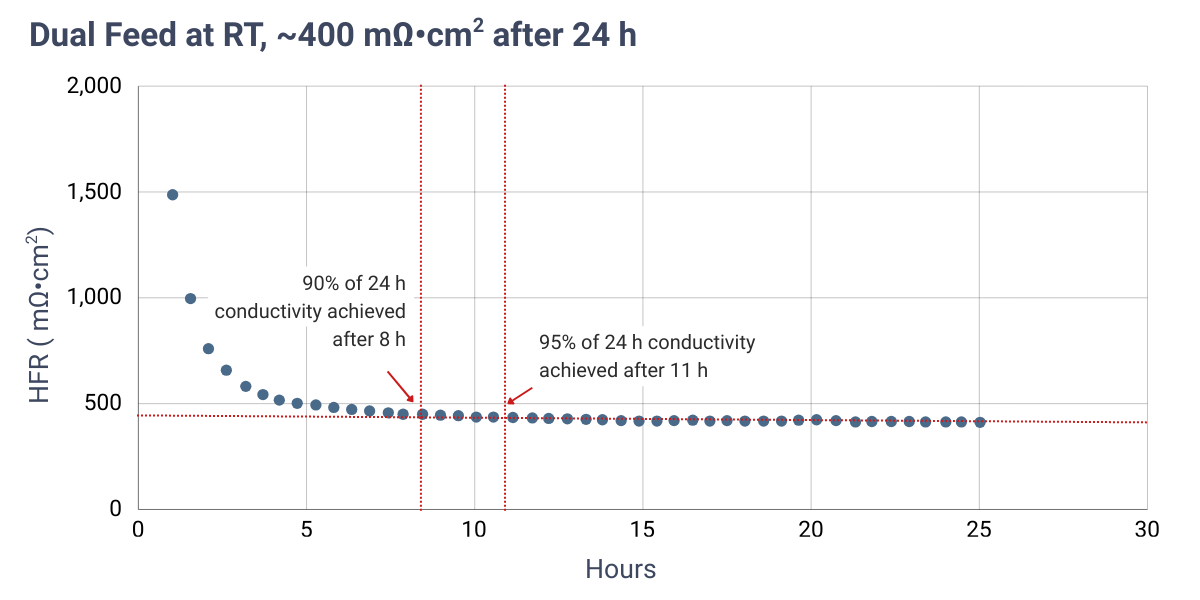
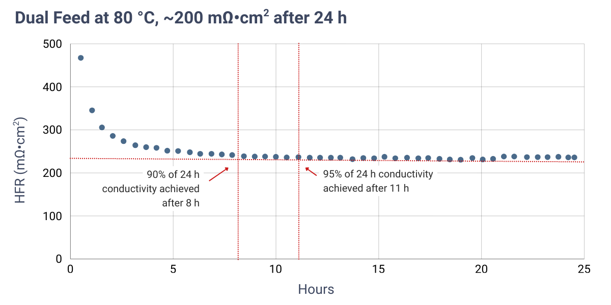
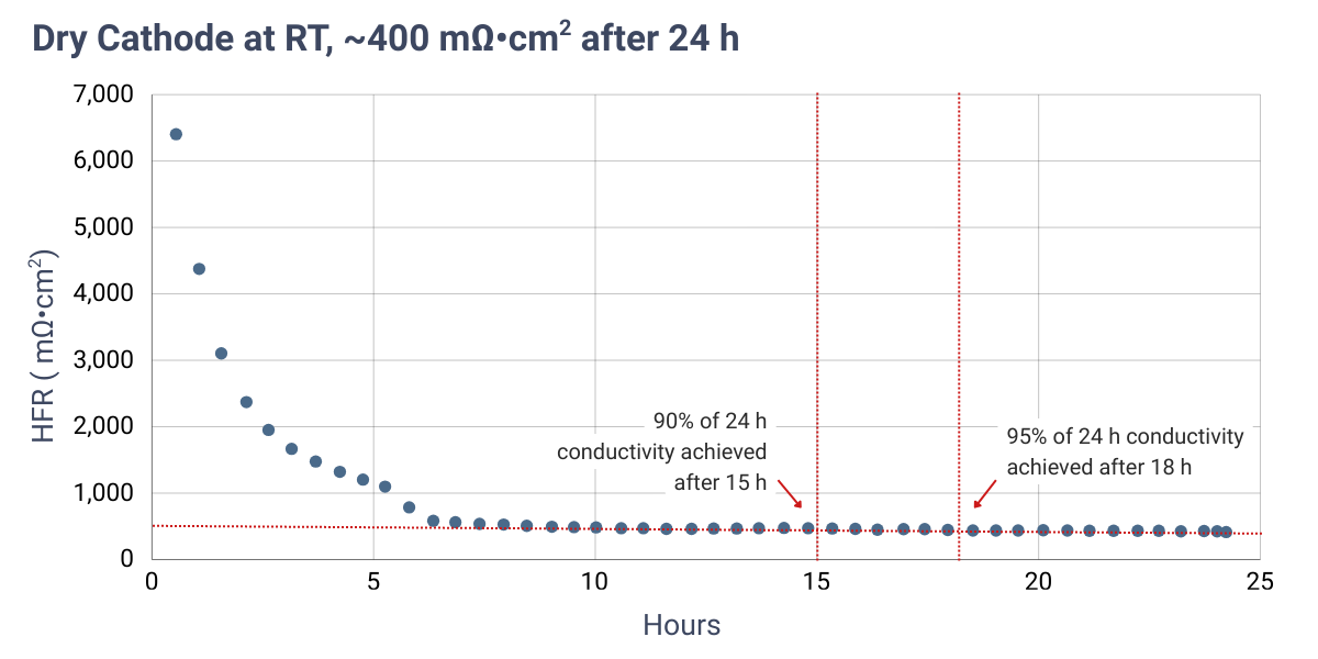

HFR measured at OCV over time using 1 M KOH under dual feed and dry cathode operation. Cells were assembled dry. Red dashed lines indicate the HFR measured after 24 hours.
Verify Conversion and Electrical Readiness
Verify successful conversion to the hydroxide form by measuring the membrane conductivity or the cell high-frequency resistance (HFR) using electrochemical impedance spectroscopy (EIS). The expected membrane HFR under fully activated conditions is typically <200 mΩ·cm2. Note that measured HFR values may be higher depending on contact resistances from cell hardware and the measurement configuration.
- Dual feed protocols generally reach the target HFR faster.
- Dry cathode configurations may require longer activation times.
- Compare measured HFR values with reference measurements obtained after 24 hours of activation.
Mounting
Mount membranes preferably in the wet state after activation to minimize mechanical stress caused by drying.
Recommended Activation & Handling Steps before use in Fuel Cells
For AEM fuel cell applications use the following general pre-treatment approach:
- Soak for at least 24 hours, and up to 36–48 hours is recommended.
- Exchange into KOH first may aid subsequent exchanges (e.g., sulfate).
Spray-Coating Catalyst Layers onto AEMION+ Membranes (CCM Preparation)
Optimized process for spray-coating catalyst layers directly onto ion-exchange membranes (e.g., Aemion⁺) using a Sono-Tek ExactaCoat or similar system
Quick overview (click to expand)
- Preheat to ~70 °C, fix membrane flat, avoid air gaps.
- Ink flow ≤ 0.8 mL min⁻¹; head speed ≤ 75 mm min⁻¹.
- Multiple light passes; rotate 90° periodically; repeat for second side.
- Dry gently; avoid excessive heat or strong airflow.
Preparation
Preheat to ~70 °C. Fix membrane flat with small (heat-resistant) tape at corners.
- Use a porous heat-transfer layer to avoid air gaps.
- 0.5 cm uncoated border; ≥ 2 cm mask overlap.
- Mild tension or a template frame to prevent curl.
Ink Loading
Load ≈ 25 mL ink, purge air, and use toggle to verify steady flow and a consistent spray pattern.
Coating and Feed / Flow Rate
- Flow: ≤ 0.8 mL min−1
- Head speed: ≤ 75 mm min−1
- Keep surface at ~70 °C throughout.
- Prefer multiple light passes to avoid pooling.
Layer Uniformity
- Pause every 1–2 runs for visual inspection.
- Adjust flow/pattern if unevenness appears.
- Rotate the membrane 90° every 5–10 runs.
- Repeat to target loading.
Coating the Second Side
After reaching target loading, flip, re-mask, align with the first side, and repeat with the same parameters.
Post-Coating Drying
Dry gently until touch-dry. With high-boiling solvents, extend time slightly; avoid excessive heat or strong airflow that can deform the CCM.
Notes & Cautions
- Do not exceed 0.8 mL min−1 flow or 75 mm min−1 head speed.
- Use templates/support frames during ion-exchange and coating to minimize curling.
- Pooling or streaks mean over-deposition → reduce flow or passes.
- Membranes must be clean and lightly hydrated but free of surface moisture before coating.
Removal of the Membrane from the Backing Layer
- With clean gloved hands, hold the membrane on its backing layer.
- Using a thumb or finger, rub against the corner edge of the membrane to produce separation from the backing layer.
- Once corner separation is achieved, carefully and gently pull the membrane from the backing while holding the backer on a clean, dry surface.
- Support the membrane as you peel until it has been fully removed.
- With clean gloves, wet a portion of the membrane/backing edge with de-ionized water to aid separation. Repeat the primary method.
- If separation does not start, spritz a small amount of water near the edge and try again.
For coating AEMION® membranes after removing from the backing layer
Ensure that the membrane remains flat.
A powder-coating masking tape can be used to overlap the membrane edges prior to coating to stabilize the membrane and minimize stress lines.
Use caution when removing tape after coating, as tears may occur. Cutting off the taped section is an alternative.
Use caution to remove tape from the membrane after the coating process.
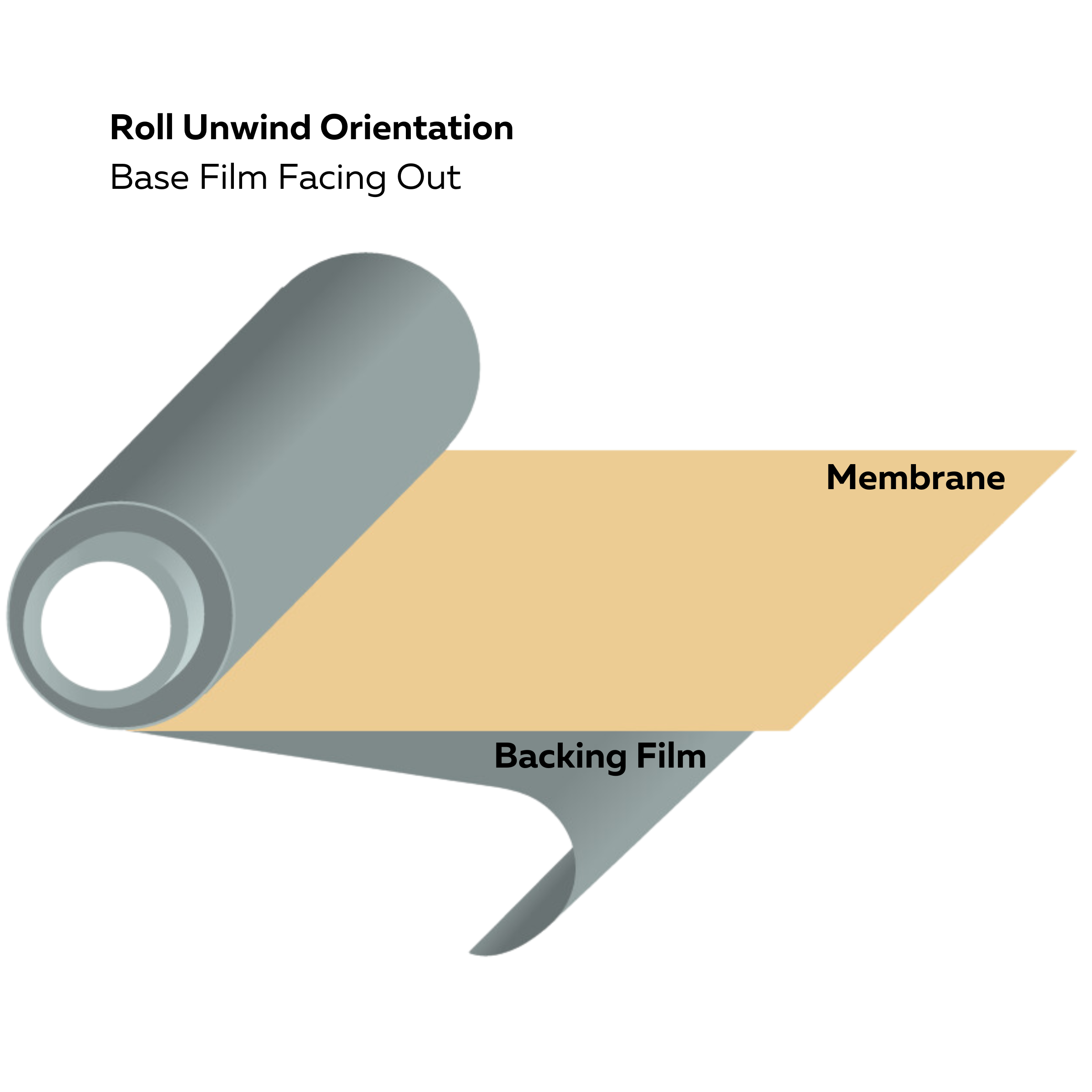
Roll unwind orientation (base film facing out)
Related Presentation
Related Blogs

How Pretreatment Affects Ion Exchange Membranes for Electrochemical Devices
This blog explores how pretreatment processes influence the performance of ion exchange membranes in electrochemical devices, highlighting the importance of proper conditioning to achieve consistent efficiency and durability.
Non-Disclosure Agreement
This is a proprietary product from Ionomr; a signed NDA between the end customer and Ionomr is required before shipment for either commercial use or research.
The NDA prevents reverse engineering and public disclosure. It does not restrict patenting, but treats the physical materials and their composition as confidential—preventing specific disclosure in a patent or otherwise—while still allowing reference to an AEM (e.g., Aemion) by trade name. Test results are confidential and require approval from both parties for disclosure. We are not concerned about blocking publications and will advise if better results appear achievable.
We also use a more explicit Materials Transfer Agreement (MTA) for academic or research organizations that further details materials IP and publication. Please find the NDA here and include it when requesting quotations.