- Home

- Products
- Molding Compounds
- Semiconductor Epoxy Mold Compounds
- Hysol GR825-73B | Black Epoxy Mold Compound
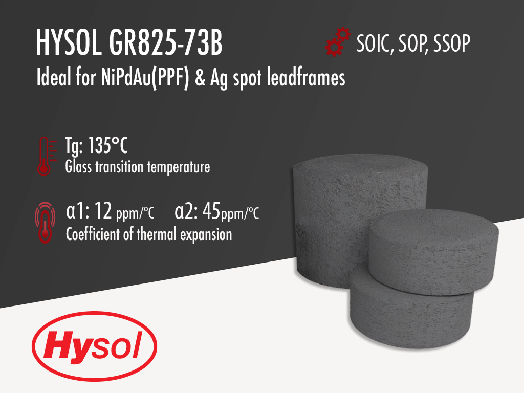
Hysol GR825-73B | Black Epoxy Mold Compound


- MSL 1 260°C
- Designed for SOIC, SOP, SSOP & QSOP
- Ideal for NiPdAu (PPF) & Ag-spot leadframes
Product Description
Hysol GR825-73B is approaching EOL and may be discontinued by 2023. The recommended alternative for SOIC packages is Hysol GR710F
Hysol GR825-73B is a black, semiconductor grade epoxy molding compound that was designed for SOIC packages. It was first qualified as MSL1 260°C on a 14 pin SOIC package with a die size of 1.4x 0.9mm (58 x 36 mils) using a Nickel Palladium Gold (NiPdAu) leadframe, also referred to as a preplated leadframe (PPF). It has since been used in mass production on this semiconductor package. Except for SOIC, it can also be used on, SOP, SSOP & QSOP packages.
Hysol GR825-73B is an environmentally friendly "green" molding compound which contains no bromine, antimony or phosphorus flame retardant and has been used in mass scale production since 2007. GR825-73B epoxy mold compound meets UL 94 V-0 Flammability at 3mm (1/8") thickness.
Technical Specifications
| General Properties | |||||||||||
| Color Color The color | Black | ||||||||||
| Filler Content | 80 % | ||||||||||
| Specific Gravity Specific Gravity Specific gravity (SG) is the ratio of the density of a substance to the density of a reference substance; equivalently, it is the ratio of the mass of a substance to the mass of a reference substance for the same given volume. For liquids, the reference substance is almost always water (1), while for gases, it is air (1.18) at room temperature. Specific gravity is unitless. | 1.9 | ||||||||||
| |||||||||||
| Physical Properties | |||||||||||
| Spiral Flow @ 175°C | 100 cm | ||||||||||
| Chemical Properties | |||||||||||
| Moisture absorption | 0.32 % | ||||||||||
| Electrical Properties | |||||||||||
| |||||||||||
| Dielectric Strength Dielectric Strength Dielectric strength is measured in kV per mm and is calculated by the Breakdown voltage divided by the thickness of the tested material. Those two properties go hand in hand and while Breakdown voltage is always thickness dependent, dielectric strength is a general material property. As an example, the dielectric strength of Polyimide is 236 kV/mm. If we place 1mm of Polyimide between two electrodes, it will act as an insulator until the voltage between the electrodes reaches 236 kV. At this point it will start acting as a good conductor, causing sparks, potential punctures and current flow. | 37 kV/mm | ||||||||||
| Volume Resistivity Volume Resistivity Volume resistivity, also called volume resistance, bulk resistance or bulk resistivity is a thickness dependent measurement of the resistivity of a material perpendicular to the plane of the surface. | 1.1x10¹⁶ Ohms⋅cm | ||||||||||
| |||||||||||
| Mechanical Properties | |||||||||||
| |||||||||||
| |||||||||||
| Thermal Properties | |||||||||||
| |||||||||||
| |||||||||||
| Glass Transition Temperature (Tg) Glass Transition Temperature (Tg) The glass transition temperature for organic adhesives is a temperature region where the polymers change from glassy and brittle to soft and rubbery. Increasing the temperature further continues the softening process as the viscosity drops too. Temperatures between the glass transition temperature and below the decomposition point of the adhesive are the best region for bonding. The glass-transition temperature Tg of a material characterizes the range of temperatures over which this glass transition occurs. | 135 °C | ||||||||||
| Thermal Conductivity Thermal Conductivity Thermal conductivity describes the ability of a material to conduct heat. It is required by power packages in order to dissipate heat and maintain stable electrical performance. Thermal conductivity units are [W/(m K)] in the SI system and [Btu/(hr ft °F)] in the Imperial system. | 0.8 W/m.K | ||||||||||
| UL 94 Rating UL 94 Rating Flammability rating classification. It determines how fast a material burns or extinguishes once it is ignited. HB: slow burning on a horizontal specimen; burning rate less than 76 mm/min for thickness less than 3 mm or burning stops before 100 mm V-2: burning stops within 30 seconds on a vertical specimen; drips of flaming particles are allowed. V-1: burning stops within 30 seconds on a vertical specimen; drips of particles allowed as long as they are not inflamed. V-0: burning stops within 10 seconds on a vertical specimen; drips of particles allowed as long as they are not inflamed. 5VB: burning stops within 60 seconds on a vertical specimen; no drips allowed; plaque specimens may develop a hole. 5VA: burning stops within 60 seconds on a vertical specimen; no drips allowed; plaque specimens may not develop a hole | V0 | ||||||||||
| Curing Conditions | |||||||||||
| |||||||||||
| |||||||||||
| Transfer Pressure | 40 - 80 kg/cm2 | ||||||||||
| Transfer Time | 15 - 25 s | ||||||||||
