
Reliability testing
Material, Stress, Mechanical and Environmental induced mechanisms
- Home

- Semiconductors
- Reliability
- Preconditioning
Preconditioning
Preconditioning is performed to assess the reliability of the package during board assembly and recreate the conditions on the production floor, wherein the packages might be exposed to the open environment, away from their protective dry-pack bags or dry boxes, and could absorb moisture. It is not meant to be stand-alone test. From JESD22-A113F, preconditioning should be done prior to and in addition to other reliability tests.
Preconditioning Test Method for Nonhermetic Solid-state Surface Mount Devices
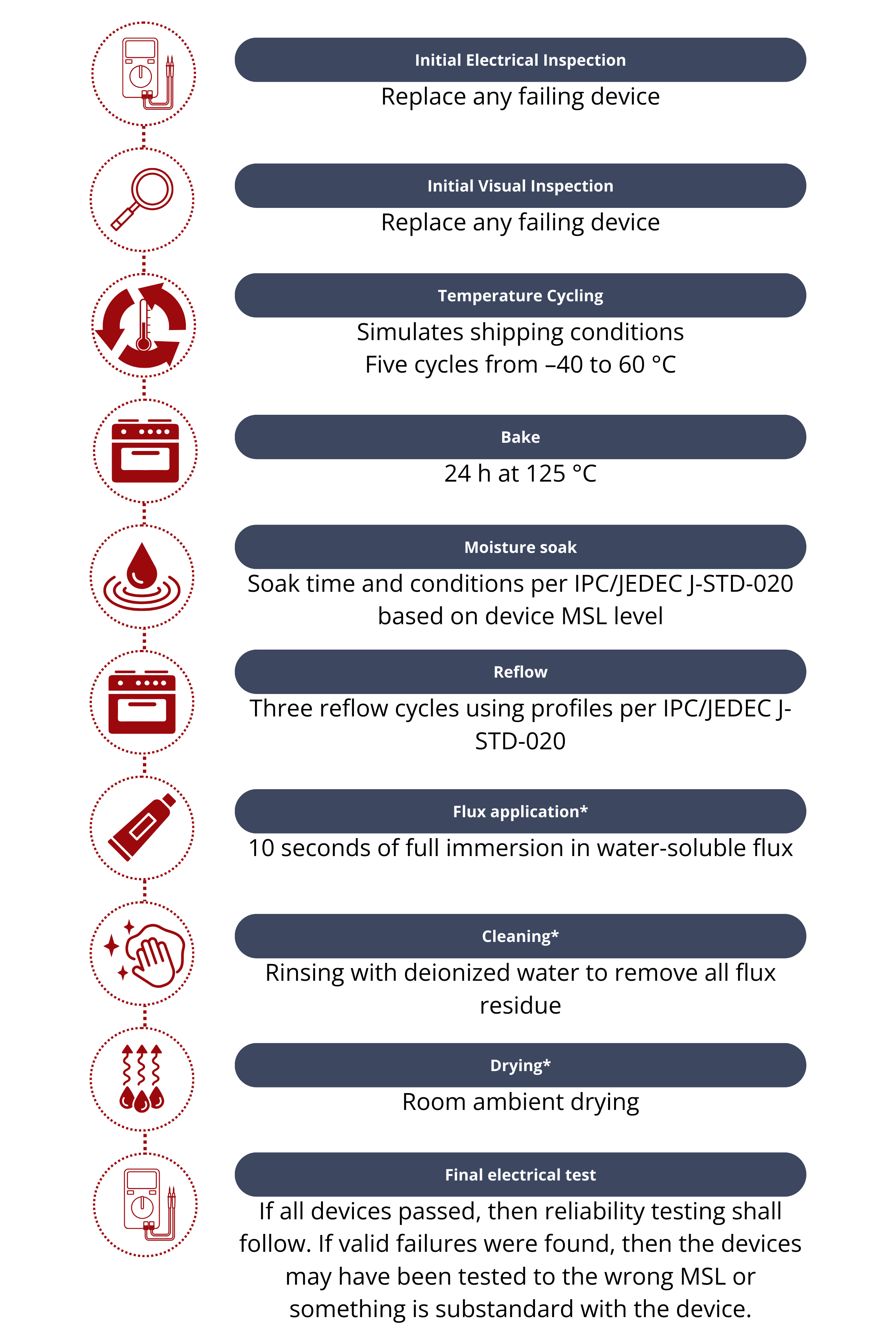
- Initial Electrical Test
Initial dc and functional tests are performed to determine if the devices meet their specifications at room temperature. Devices failing this requirement are replaced. - Visual Inspection
Conduct an external visual inspection at 40X optical magnification. Devices with cracks or other damage should be replaced. - Temperature Cycling
Perform five cycles from –40 to 60 °C to simulate conditions during transport to the customer. - Bake out
To remove absorbed moisture prior to testing, hold the device at 125 °C for 24 h. - Moisture soak
To simulate moisture absorption in the production line, soak the device according to the conditions set in JEDEC J-STD-020 for the appropriate moisture sensitivity level. Soak should be initiated within 2 h after bake out. - Reflow
After removing the sample from the temperature/humidity chamber, wait for at least 15 minutes but no more than 4 hours before exposing it to three rounds of the appropriate reflow conditions. There must be a minimum 5-minute gap between consecutive reflow processes. - Flux Application
Once the reflow solder cycles have finished, let the devices cool down at room temperature for a minimum of 15 minutes. Subsequently, apply an activated water-soluble flux to the leads of the device by immersing the entire parts in flux at room temperature for a minimum of 10 seconds. - Cleaning
Thoroughly clean the devices with multiple deionized water rinses after applying flux; no waiting time is needed. - Drying
Before reliability testing, ensure the devices are dried at room temperature. - Final Electrical Test
Perform electrical DC and functional testing on the devices as per the room temperature data sheet specifications.
*Notes: Not applicable for ball grid array (BGA), column grid array (CGA), and land grid array (LGA) packages
Source: Adapted from JEDEC, JESD22-A113F, Preconditioning of Plastic Surface Mount Devices Prior to Reliability Testing, October 2008, Annex A.1
Solder Reflow
For reflow, a solder, which can be in the form of a paste, preform, solder plating, coating, tapes and reels, wires, or spheres, is placed at each joint.2 After component placement, the boards are put into a reflow oven, where they undergo controlled heating according to a specified reflow profile. Heating mimics the activation of the flux within the solder material. The volatiles within the paste are driven off. The temperature of the joint increases up to the liquid temperature of the solder. This ultimately forms a mechanically-attached, electrically conductive pathway between the board and the attached components.3 The following are the reflow profiles for Sn–Pb and Pb-free assemblies.
Solder Reflow Profiles for Sn–Pb and Pb-free Assemblies
Condition | Sn–Pn Eutectic Assembly | Pb-free Assembly |
Minimum preheat/soak temperature | 100 °C | 150 °C |
Maximum preheat/soak temperature | 150 °C | 200 °C |
Time from minimum to maximum | 60–120 s | 60–120 s |
Ramp-up rate | 3 °C per s (maximum) | 3 °C per s (maximum) |
Liquidus temperature (TL) | 183 °C | 217 °C |
Time held above TL | 60–150 s | 60–150 s |
Peak package body temperature | 220–235 °C depending on size and volume | 245–260 °C depending on size and volume |
Hold time within 5 °C of peak temperature | 20 s | 30 s |
Ramp-down rate | 6 °C per s (maximum) | 6 °C per s (maximum) |
Time from 25 °C to peak temperature | 6 min maximum | 6 min maximum |
Source: Adapted from JEDEC, IPC/JEDEC J-STD-020D.1, Moisture/Reflow Sensitivity Classification for Nonhermetic Solid State Surface Mount Devices, March 2008, table 5-2.1
Reflow processes are typically followed by a visual inspection to confirm correct soldering of all components on the PCB and to identify any misplacements or solder issues. If any issues are found, circuit boards failing inspection are directed to a separate system for offline troubleshooting and repair.
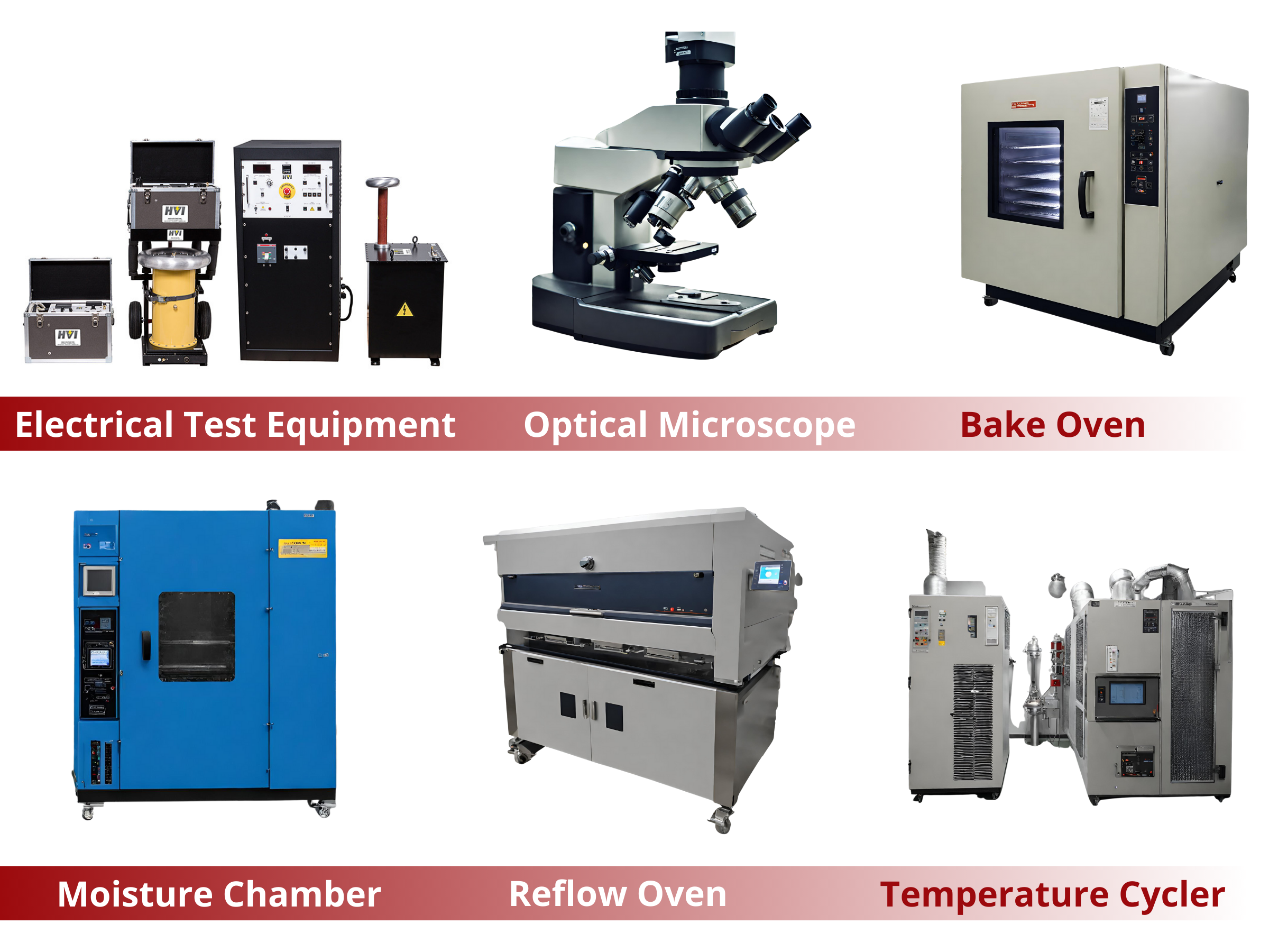
Apparatus Needed
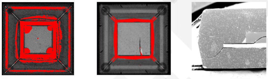
Package Failure Mode after Preconditioning: Package Cracking or Popcorning
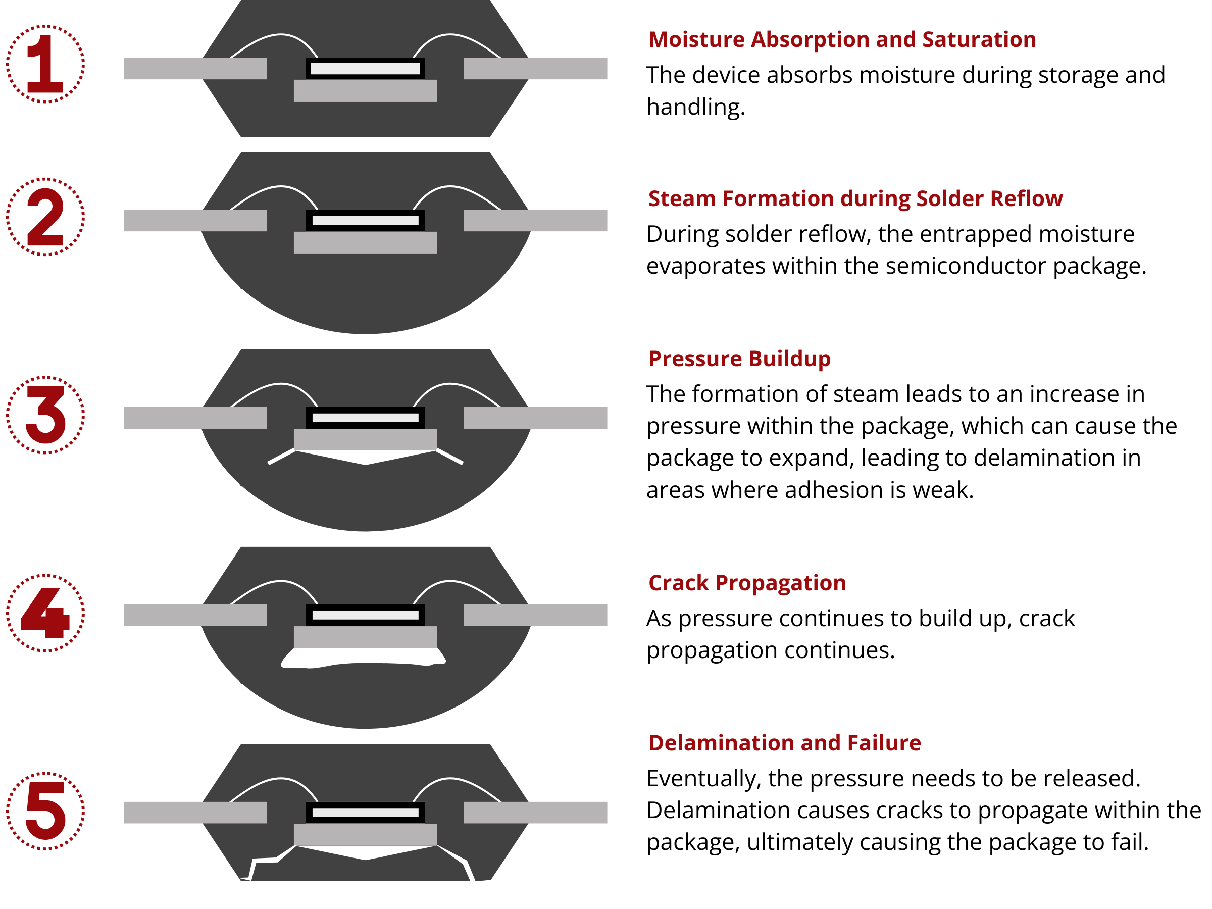
Package popcorn cracking, more commonly known as popcorning, is a failure mode often observed during solder reflow. It primarily affects moisture-sensitive semiconductor packages. This failure mode is characterized by a distinct sound resembling popping popcorn, which is how it got its name.
Stages involved in Popcorning
- Moisture Absorption and Saturation: The moisture-sensitive semiconductor packages can absorb moisture that is typically present in the environment during storage and handling.
- Steam Formation during Solder Reflow: During solder reflow, the components are subjected to elevated temperatures, which exceed the boiling point of water. This process causes the entrapped moisture to vaporize within the semiconductor package.
- Pressure Buildup: As steam is formed, pressure begins to build up in the package. This may cause the package to swell, making areas with poor adhesion to start delaminating.
- Delamination and Failure: Eventually, the pressure needs to be released. Delamination causes cracks to propagate within the package, ultimately causing the package to fail. Failure often occurs through the backside of the package, resulting in an external crack. The sound of the package failing, which resembles the popping of popcorn, gives rise to the term "popcorning."
Popcorning is a critical issue in electronic component manufacturing, as it can lead to component damage, rendering them non-functional. To prevent popcorning, manufacturers take precautions such as moisture barrier bags, humidity control, and proper handling of moisture-sensitive components to reduce moisture absorption before solder reflow.
References:
1 Chen, A., & Lo, R.H.-Y. (2012). Semiconductor Packaging: Materials Interaction and Reliability (1st ed.). CRC Press.
3 Lembersky, Michael. (2016). Realistic Cost Estimating for Manufacturing (3rd Edition) - 15.2.1.3 Solder Reflow. Society of Manufacturing Engineers (SME).