Phase Change Materials
Phase change materials (PCM) are often used as matrix materials for thermal interface applications, because they are solid at room temperature, and soften when heated. They can fully fill the gaps of contact surfaces, therefore providing a thin bondline and high reliability without pump-out issues. This is achieved by adding a TC filler to the PCM matrix which forms a phase change composite with high heat transfer performance.
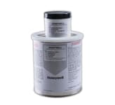
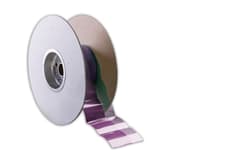
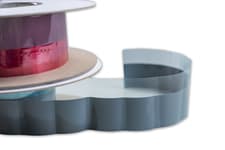
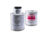
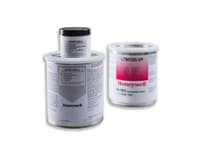
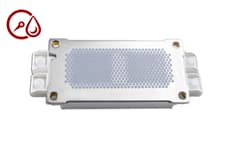
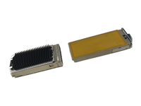
We offer silicone free, thermally conductive Phase Change Materials in both pad and paste formats. These products are designed to minimize thermal resistance at interfaces and maintain stable performance through the rigorous reliability testing required for long product life applications. Pastes are exactly the same as the pad versions with the addition of solvent that makes them screen printable and ideal for IGBT.
Based on a robust polymer PCM structure, these materials exhibit effective wetting properties during typical operating temperature ranges, resulting in very low surface contact resistance. With a breakdown temperature of ~180°C they provide superior reliability and maintain low thermal impedance, making PCM desirable for high-performance integrated circuit devices.
PTM6880 | Phase Change Pad
- 6,0 W/m•K thermal conductivity
- 0.056 ℃•cm²/W
- Improved flowability
- 12 weeks
LTM 6300-SP | Phase Change Paste
- 0.12 - 0.14 Thermal Impedance
- 1.8 - 2.4 Thermal Conductivity
- Highest volume resistivity
- 8 weeks
PCM 45F | Phase Change Pad
- 0.09 - 0.12 Thermal Impedance
- 2.0 - 2.5 Thermal Conductivity
- Pad form
- In stock
PCM 45F-SP | Phase Change Paste
- 0.09 - 0.12 Thermal Impedance
- 2.0 - 2.5 Thermal Conductivity
- High volume resistivity
- 8 weeks
PTM 5000 | Phase Change Pad
- 0.06 - 0.08 Thermal Impedance
- 3.5 - 4.5 Thermal Conductivity
- Pad form
- 8 weeks
PTM 5000-SP | Phase Change Paste
- 0.06 - 0.08 Thermal Impedance
- 3.5 - 4.5 Thermal Conductivity
- Stencil Printable
- 8 weeks
PTM 6000 | Phase Change Pad
- Higher reliability than PTM5000
- 3.5 - 4.5 Thermal Conductivity
- Pad form
- In stock
PTM 6000HV | Phase Change Paste
- 0.14 Thermal Impedance
- 5.2 Thermal Conductivity
- Optimized for IGBT
- In stock
PTM 7000-SP | Phase Change Paste
- 0.06 Thermal Impedance
- 6.5 Thermal Conductivity
- Paste form
- In stock
PTM 7000-SPM | Phase Change Paste
- 0.06 Thermal Impedance
- 6.5 Thermal Conductivity
- Medium drying solvent
- In stock
PTM 7900-SP | Phase Change Paste
- 0.045 Thermal Impedance
- 8.0 Thermal Conductivity
- Paste form
- 8 weeks
PTM 7950-SPS | Phase Change Paste
- 0.04 Thermal Impedance
- 8.5 Thermal Conductivity
- Slow drying solvent
- 8 weeks
RTM-X22 | Pluggable Phase Change Pad
- 0.7 Thermal Impedance
- >50 Pluggable performance
- 0.15 - 0.22mm Thickness
- 8 weeks
Product Selector Guide
| Product name | Specific Gravity | Thickness Range (mm) | Thermal Conductivity (W/m·K) | Thermal Impedance @ no shim (˚C·cm2/W) | Volume Resistivity (ohm·cm) |
|---|---|---|---|---|---|
| LTM 6300-SP | 1.8 | 0.20-1.00 | 1.8-2.4 | 0.12-0.14 | 3.0×10¹⁵ |
| PCM 45F-SP | 2.2 | 0.20-1.00 | 2.0-2.5 | 0.09-0.12 | 8.2×10¹⁴ |
| PTM 5000 | 2.3 | 0.20-1.00 | 3.5-4.5 | 0.06-0.08 | 2.1×10¹⁴ |
| PTM 5000-SP | 2.3 | 0.20-1.00 | 3.5-4.5 | 0.06-0.08 | 2.1x10¹⁴ |
| PTM 6000 | 2.3 | 0.20-1.00 | 3.5-4.5 | 0.06-0.08 | 2.1×10¹⁴ |
| PTM 6000HV | 2.6 | 0.20-1.00 | 5.2 | 0.09 | 2.1×10¹⁴ |
| PTM 7000 | 2.7 | 0.20-1.00 | 6.5 | 0.06 | 2.1×10¹⁴ |
| PTM 7000-SP | 2.7 | 0.20-1.00 | 6.5 | 0.06 | 2.1x10¹⁴ |
| PTM 7000-SPS | 2.7 | 0.20-1.00 | 6.5 | 0.06 | 2.1x10¹⁴ |
| PTM 7900 | 2.8 | 0.20-1.00 | 8.0 | 0.045 | 2.1×10¹⁴ |
| PTM 7900-SP | 2.8 | 0.20-1.00 | 8.0 | 0.045 | 2.1x10¹⁴ |
| PTM 7950 | 2.8 | 0.25 | 8.5 | 0.04 | 2.1×10¹⁴ |
| PTM 7950-SPS | 2.8 | 0.25 | 8.5 | 0.04 | 2.1x10¹⁴ |
Frequently Asked Questions
Frequently asked questions about Phase Change Materials
What are some typical PCM applications?
Typical phase change material Applications include:
- Power control unit, inverter, onboard electronics, IGBT
- Auto electronics, traction power inverters, transmission, rechargeable energy storage systems, cockpit electronics, engine control systems, on board charging modules
- Servers, supercomputing, video graphic array (VGA) cards, AI, GPU/CPU/Desktop, solid state drives (SSD)
- Switches, routers, base stations
- Tablets, gaming, notebooks, smartphones, action cameras & lighting
What controls the viscosity of PCM paste versions?
PCM paste is typically mixed from two components:
• A bulk material consisting of polymer resin and thermally conductive fillers
• A solvent component, which is added to help control the viscosity
Why choose PCM over Thermal grease?
One can say that it comes down to preference, but it really doesn\'t. Phase change materials are hands down the best materials you can use as thermal interface IF the application parameters allow it. They are clean, efficient,can achieve the thinnest bondlines out of any other materials and are silicone free. Power cycling? Phase change can easily handle it while thermal grease can be pushed under the chip after a few hundred cycles.
Additionally they come into both paste (stencil print and dispence) and pad form (0.2~1mm thickness) and their Silicon free chemistry can achieve a bondline of 20~30μm making it the thinnest, cleanest and most reliable bondline in the market. Does this make thermal grease bad? Definitely not. Grease is great for all the other application types that PCM can\'t cover due to the temperature restrictions.
What is the potlife of the PTM7XXX-SP?
Potlife (also referred to as work life) refers to the amount of time the material can be still be used after it has been opened. When kept in the 1kg cans, the potlife is 12 hours from the time the can is opened. When the lid is replaced and the can is closed again, you will have 48 hours to use the balance of the material. The remaining material should also be remixed (or re-rolled on a jar roller) prior to use.
Similarly, in the 280cc cartridge, the potlife is 24hrs if dispensed from the cartridge directly. If the cartridge is opened to add material to the printer and then closed again, the balance of the material should be used within 24-36 hours.
How should I clean Stencil printable PTM?
There are several ways to clean the stencils and printing tools while using PTM pastes or to clean heatsinks and modulus boards during rework. These solvents need to be carefully cleaned with a Non-woven antistatic microfibre (lint-free) cloth.
From "safe" options, the best solvents are IPA (isopropyl alcohol) and Isopar M (brand solvent containing small amounts of Naphtha). These are the most suitable for cleaning.
Naphtha and toluene are the best and most efficient solvents for removing phase change materials during reworking, but they have the downside of being carcinogenic and should be handled with care. You could also try Acetone and ethanol but they will not be as good as IPA and Naphtha.
What happens to Phase Change Materials after Shelf Life?
Past the shelf life, the most readily observed response is precut pads (kiss-cut) tend to stick to each other and customers may have difficulty peeling out one without damaging adjacent one. There will be some viscosity change that may or may not affect thermal performance and we will not test or recertify material. We will not be liable for product quality or performance if expired parts are used in manufacturing.
Why are some properties a range?
Phase change materials come in thicknesses ranging from 0.2-1mm. Those are the initial values that are adjusted after you heat up (>45°C) and pressure the material. The installation pressure will determine the final thickness and thermal properties that those materials will keep throughout their lifetime. Thermal conductivity and bond line are directly affected by the installation pressure and no matter the stated properties, the final bondline is what is going to determine the material\'s thermal fate.
What is the thickness before and after the PTM7XXX-SP paste drying?
It is typical to lose approx. 20% thickness due to solvent drying. For example, a 300µm (0.3mm) thickness stencil of wet PTM7XXX-SP will result in 240µm (0.24mm) after drying. If the thickness loss is more than 20%, then the can was not stirred or rolled and it is indicative of mixing issues prior to dispensing them on the printing equipment.
What are the differences between Pads and Pastes?
Phase change Pastes have the exact same chemistry as the phase change pads, with added solvent to make them printable. Stencil print is highly sought after for applications with high throughput such as IGBT screen printing.
Solvents can be adjusted so that the drying process is faster or slower, depending on your application requirements.
What is the maximum operating temperature of the Phase Change Materials?
Though the maximum operating temperature for our Phase Change Materials is approximately 150°C. It is not recommended to operate continuously for long period of time above 125°C.
Should I use a silicone-based or silicone-free TIM?
There are pros and cons to using both a silicone-based or silicone-free Thermal Interface material. For more information on this, we have written a blog Silicone vs Silicone-free TIMs Advantages of Different Materials which discussed the properties of both materials on thermal management.
What is the cool down period after 60C/30 minutes for the material to completely set?
Phase change material doesn’t permanently set or cure like some other materials. It remains soft and pliable, meaning it does not have a specific "cool down" period in the traditional sense, as it's designed to accommodate thermal expansion and contraction throughout the lifecycle of the device. Once the material has spread at the desired temperature, it will continue to perform under various thermal conditions
Does the material never sets and just keeps expanding/contracting with the heat/cooling?
The phase change process of the material is a reversible process meaning, it continuously expands and contracts with the device's heat cycling. It does not permanently harden or cure, which allows it to maintain effective thermal contact over time
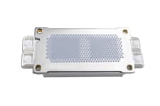
Why is a honeycomb pattern commonly used in paste printing?
The honeycomb pattern is preferred in paste printing because it provides excellent coverage while using less material, ensures uniform distribution, and improves stencil release compared to solid fills. Its geometry allows the paste to spread evenly during compression, minimizing voids, squeeze-out, and defects.
Learn More
Phase Change Materials
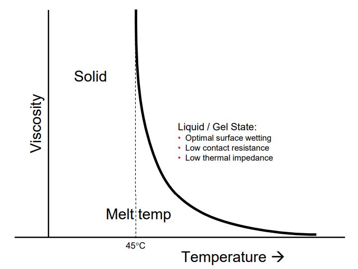 Figure. Temperature vs. Viscosity
Phase change materials (PCM) are often used as matrix materials for thermal interface applications, because they are solid at room temperature, and soften when heated (>45 °C). Those Silicone free chemistries rely on thermally conductive fillers such as ZnO, Aluminium and Alumina to achieve their thermal properties (Blog indepth discussion: Silicone vs Silicone-free TIMs Advantages of Different Materials) . Phase change material (PCM) are provided both in pad and paste forms. Pastes are exactly the same as pad versions with additional amount of solvents that make them screen or stencial printable and ideal for automatic production processes.
Thanks to the viscosity drop while increasing the temperature (>45°C) and optimal surface wetting property, the PCM could spread and fully fill the small gaps between contact surfaces, therefore provding a thin bondlines, even 20-30μm. PCM are designed to minimize thermal resistance at interfaces and maintain stable performance through the rigorous reliability tests required for long product life applications.
Their nature doesn't work for high operating temperature applications above 150°C but if the temperatures allow, it is a much better alternative for thermal grease since they are not prone to pump or dry out and are not "messy" at all. They definitely tick the boxes for conformable and reliable.
Why is PCM more reliable than other TIMs?
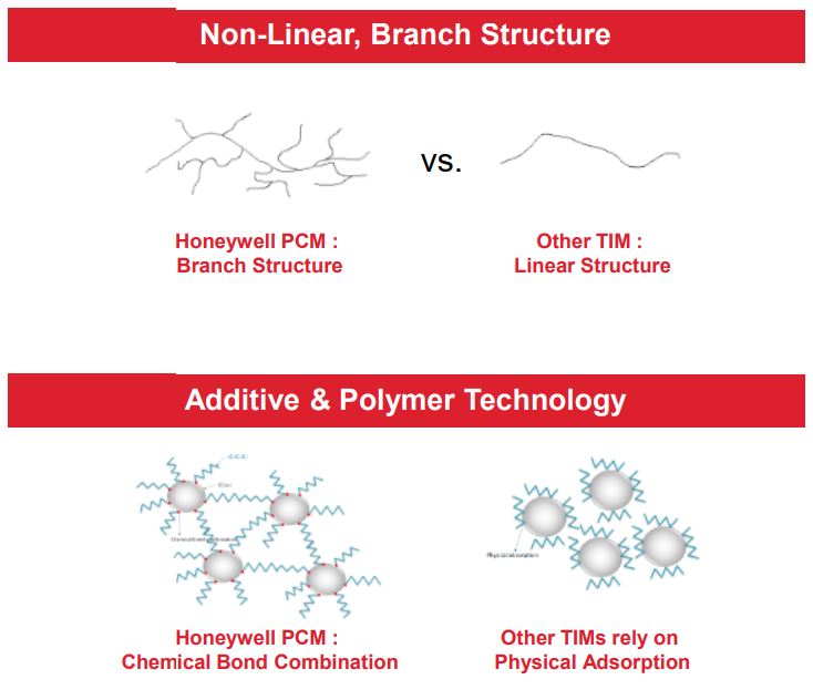
Compared to other type of TIMs (thermal interface materials) such as silicone grease, PCM have longer molecular chains with high molecular weight and surface tension ensuring a robust polymer structure and a stable filler-polymer matrix to avoid filler migration and separation. The H steric hindrance provides a rigid structure that ensures low filler migration and separation that at the same time limits the material mobility and pump out.
On the other hand, the tried and proven thermal grease has good flowability and low contact resistance but its short chains and Si-O-Si structures create a less rigid structure that has potential for migration, dry out and pump out issues.
To sum up, phase change materials exhibit the following characteristics:
- Optimal surface wetting
- Low contanct resistance
- Low thermal impedance
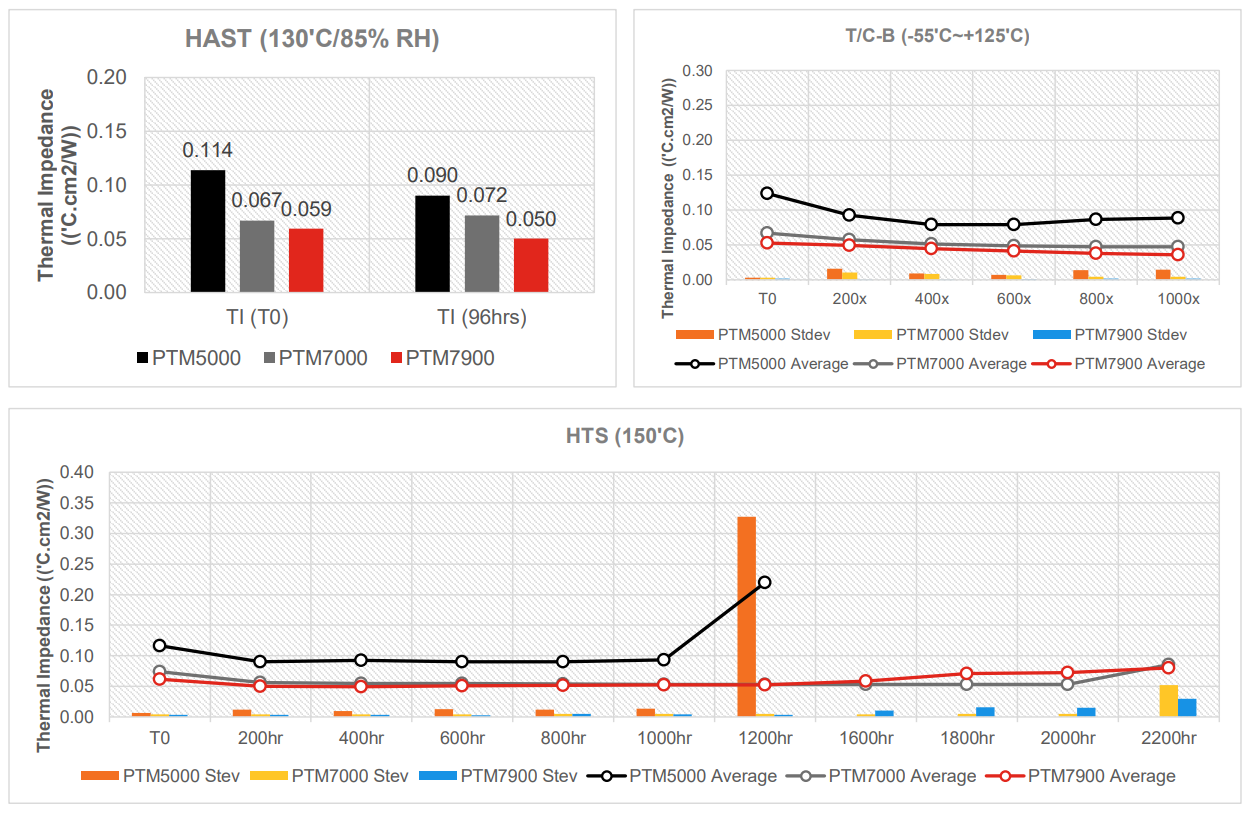
- Stable thermal impedance across reliability tests
- No bleed out, pump out and flow out
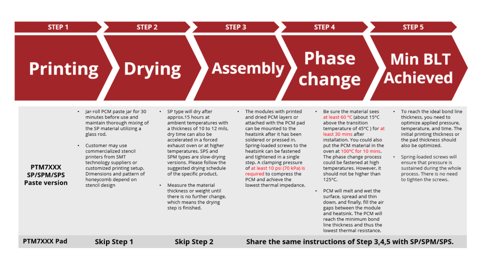
How to apply PCM pastes & pads?
Phase Change Material Application Notes
At what temperature does Phase Change occurs?
The phase change temperature is a critical characteristic of phase change materials. It refers to the specific temperature at which the material undergoes a phase transition. For Honeywell Phase Change Materials, the average phase change temperature is around 45 °C. This temperature is a result of the composition of polymeric paraffin waxes within the materials and is considered the average for the phase transition.
The actual/accurate Phase Change Temperature however is routinely assessed for each batch using Differential Scanning Calorimetry (DSC) at peak temperature (see highlighted DSC at the attached sample certificate of analysis), and it is ideally range between 37.5 °C and 52.5 °C to meet acceptable standards. Therefore, we recommend conducting the assembly at temperatures exceeding 60 °C to guarantee the material undergoes the desired phase change.
Table 1: Honeywell Inspection Result of PTM6000HV-SP Syringe
| Parameter | Unit | LSL | USL | Data |
| Thermal Impedance (No Shim) | ℃•cm2/watt | — | 0.12 | 0.073 |
| Thermal Impedance (2 mil Shim) | ℃•cm2/watt | — | 0.25 | 0.132 |
| DSC Measurement (peak temperature) | ℃ | 37.50 | 52.50 | 41.040 |
How long does it take for the material to fully phase changed at different temperature?
To support the time indicated in "Step 4" of Application of PCM. Experimental data below shows the time it takes for the material to fully phase changed or can be interpreted in the data as the minimum BLT point at varying temperatures..png)
.png)
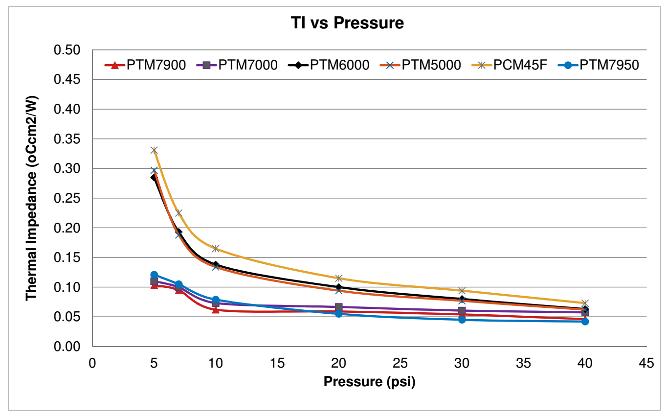
PCM Products Thermal Performance And Reliability
.png) | .png) | .png) | .png) |
PCM Paste Stencil Printing Process (SP)
Stencil printable Phase change materials require the following steps for a successful application:
- Stencil print. “SP” or “SPS” versions of Phase Change Materials contain solvents which allow the paste to be stencil printed.
- Dry. Stencil-print Phase Change Materials require a drying step to remove the solvent prior to application. This drying time depends on the selected temperature.
- Apply Pressure. Phase Change Materials require pressure to reduce the thermal impedance. A minimum pressure of 70kPa (10psi) is required and must be applied after the drying phase and during assembly.
Step 1: Storage & Jar Rolling
PCM paste does not need to be refrigerated at 5˚C, it needs to be stored at RT (room temperature) with the lid tightly sealed. If stored at 5 ˚C, it would need 4~5 hrs thawing and mixing at RT before it can be used. Otherwise, the bad homogenization could cause spreading problems. Its shelf life is 12 months at RT.
You should Jar-roll PCM paste jar for 30 minutes before use .After jar-rolling and just before printing, maintain thorough mixing of the SP material utilising a glass rod.
Step 2: Stencil Printing Guidelines for Phase Change Materials (PCM)
When stencil printing PCM, follow these guidelines based on SMT (Surface Mount Technology) best practices for solder paste. These steps ensure accurate paste deposition, minimal waste, and reliable results.
Table 2: Stencil Printing Guidelines
| Guideline | Description | Formula |
| Aspect Ratio | Ensure the aspect ratio (width of stencil opening ÷ stencil thickness) is greater than 1.5 for effective paste release. Example: The print width is 40 mm and the final dried height is 0.2 mm. | .png) |
| Area Ratio | Ensure the area ratio (print area ÷ wall area of the stencil aperture) is greater than 0.66. Example: A 46 x 40 mm print area with a stencil thickness of 0.25 mm | .png) |
| Compensate for PCM Shrinkage | PCM shrinks by approximately 20% after drying. To achieve the final target height, set the initial print height 20% higher. Example: If the desired dried height is 0.20 mm, the initial thickness is 0.25mm. |  |
| Calculate the Estimated Paste Volume | To minimize waste, calculate the required paste volume using the print area and the initial stencil thickness. Example: For a print area of 46 x 40 mm and an initial thickness of 0.25 mm, the print area is 1840 mm2 and the initial volume is 460 mm3 |  |
| Adjust for Process Losses (Optional) | To account for slight inefficiencies, add a small margin (typically10–20%) |
.png)
Worked Example
Given the following material with a target print dimensions of 46 mm (L) x 40 mm (W) x 0.2 mm (Final Dried Height):
| Stencil Thickness | 0.25 mm |
| Aspect Ratio | 200 (satisfies >1.5 guideline) |
| Area Ratio | 42.8 (satisfies >0.66 guideline) |
| Estimated Paste Volume | 460 mm³ (506 mm³ with 10% margin for losses) |
Factors Affecting Stencil Printing
The paste deposition process is widely regarded as a significant contributor to defects in the assembly process. Like all manufacturing operations, paste printing is influenced by both special and common cause variations. These variations stem from numerous factors, including the paste material, squeegee blade type, stencil aperture layout, and printing parameters such as speed, blade angle, and print pressure.
In one particular inquiry, an issue with automated printing was observed where the squeegee blade appeared to pull an excessive amount of paste away from the stencil at the end of the printing stroke, a phenomenon referred to as "thieving." The initial recommendation was to apply the "right amount of paste" to the squeegee to mitigate thieving, but this approach did not resolve the issue.
A common challenge in paste printing is the discrepancy between theoretical expectations and actual performance. Ideally, the squeegee blade should push the paste forward and downward into the stencil apertures (as shown in the diagram below). However, in practice, the paste roll is often forced upward along the squeegee blade during the printing stroke.
This results in paste adhering to the blade instead of being deposited into the apertures. When the blade lifts from the stencil, the retained paste further exacerbates the problem by reducing the size of the paste bead. Consequently, this insufficient paste bead leads to inadequate stencil filling, potentially causing defects in the final assembly.
One approach to mitigate this issue is to use a profiled blade instead of a classic squeegee blade (refer to the diagram).

The profiled blade redirects the force of the paste roll back down, enhancing the paste roll and improving aperture filling.
This adjustment can increase print speeds and improve transfer efficiency, potentially resolving some of the defects encountered.
Other parameters that can be looked into are:
1. Reduce Blade Pressure: Excessive pressure squeezes the paste against the stencil, forcing it up the blade and causing it to stick. Lowering the pressure allows the paste to roll naturally.
2. Decrease Blade Angle: Adjusting the blade angle from your current 55° to 50° could improve the paste's rolling behavior and reduce the likelihood of it climbing up the blade.
Based on studies, an angle range between 50°–60° provides an optimal attack angle for achieving a good print profile.
3. Increase Squeegee Speed: Faster strokes promote consistent paste rolling and reduce adhesion to the blade. However, over speeding may cause incomplete stencil filling.
Step 3: Solvent Drying
Approximate recommended drying times for PTM-Series Stencil Print (SP) type Phase Change Material (based on 0.25mm – 0.3mm thickness):
- 15 hours @ 25°C
- 3.5 hours @ 50°C
- 20 mins @ 80°C
- 2-3 mins @ 100°C
Please note that times are based on the part's temperature and are best measured using a thermocouple.
As a pro tip, it is also possible to determine the time required based on the 20-22% height reduction of the Phase Change Material. Different types of Stencil Print materials will dry in different times and temperatures. We generally offer SP, SPM and SPS version. You can imagine them as Normal, Medium and Slow dry. In Room temperature, normal pastes dry pretty fast, at ~2.5 hours. Medium pastes can take up to two days while Slow versions can dry for more than two days... Of course this changes into minutes at 100°C. At 100°C, Normal ones take ~2.5minutes, Medium ones ~7 minutes and Slow ones can take more than 10 minutes to dry.
.png) Figure. Solvent evaporation vs. Time in open air at 25℃.
Figure. Solvent evaporation vs. Time in open air at 25℃.
.png) Figure. Solvent evaporation vs. Time in open air at 50℃.
Figure. Solvent evaporation vs. Time in open air at 50℃.Thickness Shrinkage
| Sample# | Thickness right after print (mm) | Thickness after Solvent dry (mm) | Height reduction |
| 1 | 0.299 | 0.239 | 20.07% |
| 2 | 0.247 | 0.195 | 21.05% |
| 3 | 0.194 | 0.154 | 20.62% |
All of our PCM materials come in both Pad and Paste versions (SP). The SP versions are identical to the pads, with the main difference being the added solvent that makes them more viscous. With this form come a couple of questions, first one being, "How much does the solvent shrink and how does this affect the final bondline thickness?".
To answer this we printed in a few different target thicknesses, namely 0.2mm, 0.25mm and 0.3mm. Then we put these samples in the oven for 20 minutes at 80°C for the solvent to dry and measured the outcome. From the resulting thicknesses, we concluded that, regardless of the print thickness, the dry version is ±20% thinner than the thickness right after print. So, for example, to get a 0.25mm final (dry) bondline we need a 0.3mm initial thickness.
Step 4: Mounting and Assembly
Phase Change Materials require pressure for the lowest possible Thermal Impedance. Some application parameters that we should take into account are the following:
• We require clamp pressure of at least 10 psi (70 kPa) to compress the PCM and achieve the lowest thermal impedance and thus the best thermal performance.
The modules with printed and dried PCM layers can be mounted to the heatsink after it has been soldered or pressed in. Spring loaded screws to the heatsink can be fastened and tightened in a single step. The PCM is solid at room temperature. Screws can be tightened immediately without any relaxation time.
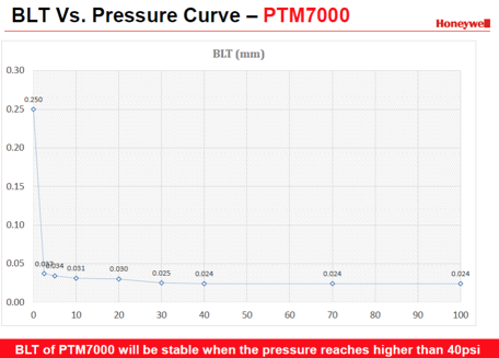
• PCM is not compressible at room temperature, but gel like above 45°C and thins down with temperature and pressure increasing.
To achieve the lowest thermal impedance and thus the best thermal performance, check the pressure and thermal impedance curve below.
• Once the module has been mounted, the system should be heated up while leaving enough time for PCM to melt.
Be sure the material sees at least 60°C (about 15°C above transition temperature of 45°C ) for at least 30 mins after installation.ensure that pressure is sustained.
Phase change materials will melt, spread, fill gaps and provide an optimal thermal connection between module and heatsink. Spring loaded screws ensure that pressure is sustained.
.png)
Figure. Applied pressure vs. Thermal impedance
If we observe the results of applied pressure on a PTM7000 phase change material we can see that when a PCM pad is installed and compressed under pressure, temperature and time, it will become thinner and spread out.
Typically, most customers use an initial pad size that is 70-80% of the target area to accommodate this spread, when the initial thickness is 0.2mm. You will have to determine the ideal size for your application in a way that fits the equipment in your assembly line.
Final Bondline Thickness
To reach your ideal bondline thickness, you need to work towards it with the aforementioned trinity of parameters, pressure, temperature and time. Normally, 30~40psi pressure is ideal for the initial step. Then you can leave the material at 60℃ for at least 30 mins after installation to settle. If low pressure such as 10psi, is applied it is better to increase the temperature (80~90℃) and extend the time (1 hour).
All in all this is a clear and cookie cut process that needs to be adjusted to your specific needs. Feel free to contact us with your application requirements and our technical team will direct you to the correct product and printing parameters.
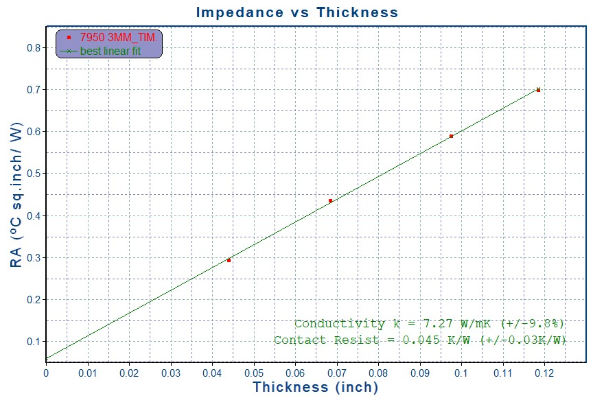
When evaluating the thermal performance of thermal interface materials (TIMs) like, we collect thermal impedance (TI) data across different thicknesses of the material. By plotting this data, we generate a linear relationship between thermal impedance and bond line thickness (BLT).
The graph show the relationship between thermal impedance (RA) and thickness for a TIM. The green line indicates a linear fit to the data points. The slope of the line in this graph (RA vs. thickness) represents thermal resistance per unit thickness (in °C·in²/W/inch). The thermal conductivity (k) is then calculated based on the slope using standard thermal equations.
Contact resistance (°C·cm²/W) can also be interpreted in this graph as the intercept of the linear fit (where the line intersects the y-axis)
Case Study: Re-evaluating Expired PCM, When Is It Still Safe to Use
Currently, our Phase Change Materials (PCM) have a shelf life of up to 12 months under recommended storage conditions. However, there are instances where customers encounter expired stock beyond this period and inquire whether the material is still usable.
To support informed, data-driven decisions, Honeywell has conducted internal testing using retained samples beyond the shelf life stored at our manufacturing facility. The objective is to evaluate whether PCM materials beyond their stated shelf life still meet key performance criteria.
The following tests were performed:
- Thermal Impedance Testing (with and without shim), aligned with Certificate of Analysis (CoA) standards
- Viscosity Measurement to assess flow and printability
- Specific Gravity Testing to monitor composition consistency
- Moisture Content Analysis to check for degradation due to humidity exposure
These evaluations help determine whether the material remains within acceptable performance limits and can be conditionally approved for use in non-critical or internal applications.
Identified Samples
We have identified the oldest Lots we have on hand:

Results
Table: Thermal Impedance & Viscosity
Lot | Retest TI with shim | COA TI with shim | Retest TI No shim | COA TI No shim | Retest Viscosity | COA Viscosity |
H7SP30905A | 0.153 | 0.108 | 0.046 | 0.056 | 84 | 83 |
H7SP31114A | 0.138 | 0.131 | 0.052 | 0.047 | 81.5 | 75.5 |
H7SP31115A | 0.146 | 0.148 | 0.051 | 0.033 | 84 | 80 |
Table: Moisture & Specific Gravity Test
Lot | Sample ID | Moisture (ug/g) | Density (g/cc) |
1 | H7SP30905A | 730.2 | 2.347 |
2 | H7SP31114A | 733.9 | 2.341 |
3 | H7SP31115A | 634.9 | 2.345 |
Based on the Thermal Impedance retest, the results remained well within specifications when compared to the original values recorded in the Certificate of Analysis (CoA). In fact, the values were found to be nearly identical, indicating no significant degradation in thermal performance despite being beyond the 12-month shelf life.
However, some moisture was observed in the expired PCM material. This can be explained by the inherent properties of the material components:
The polymer matrix is non-polar and hydrophobic, meaning it naturally repels moisture.
The filler, on the other hand, is polar and hydrophilic, making it more prone to moisture absorption over time.
During extended storage, especially in less-than-ideal conditions, the filler may gradually absorb ambient moisture, which could affect consistency or long-term reliability depending on the application.
The data and observations provided are intended to support engineers in making technically informed decisions when evaluating the potential use of PCM materials beyond their specified shelf life. However, CAPLINQ and Honeywell do not guarantee product quality, reliability, or performance if expired materials are used in manufacturing processes. Use of such materials is at the customer’s own risk, and any deviation from the recommended shelf life or storage conditions remains the sole responsibility of the end user.
Case Study: Measuring Bond Line Thickness of Phase-Change Material with Non-Planar Substrate
Accurate bond line thickness (BLT) measurement is essential when validating the thermal performance of phase-change thermal interface materials (TIMs) such as PTM7950. However, obtaining reliable measurements becomes more challenging when the substrate includes curvature designed to replicate die warpage in real semiconductor packages.
This case study documents a customer’s measurement issue, investigates the root causes of unexpected negative thickness readings, and presents a validated, repeatable method to characterize phase-change behavior on non-planar geometries.
Shim-Based Zeroing Method
To eliminate negative readings and stabilize the measurement reference, we recommended introducing a thin, non-compressible shim during the zeroing process.
Step 1: Zeroing With Shim

The shim is only used to establish the reference (zero).
Place the shim (typical thickness 25–50 µm) between the cold plate and the aluminum block without the TIM, then set the gauge to zero.
This ensures that “zero” corresponds to a small, known separation — not full metal contact.
Step 2 : TIM Measurement
Remove the shim and insert the TIM sample instead.
Run the test under the same load and temperature conditions.
The gauge now measures the true compression and thickness change of the TIM as the load and temperature are applied.
Because you already know the shim thickness (25 - 50 µm), you can correct your absolute thickness values by that known offset if needed.
This set-up prevents false negative readings caused by fixture expansion or micro-deformation at a metal-to-metal interface.
The shim is not part of the actual test, it’s removed before measurement, so it does not interfere with the TIM’s phase change or the final bond-line thickness reading.
Additional notes for this set-up:
- Shim material that can be used are thin stainless shim or Kapton/Polyimide shim works well. Choose something stiff and non-compressible at the forces you use.
- Verify with a control: after zeroing with shim, remove shim and run a “no TIM” control (only metal-metal at test load) while heating to 60 °C to quantify thermal/fixture drift.
This helps separate true TIM compression/flow from fixture expansion. - For data correction, subtract the shim thickness from final steady-state displacement if you want absolute bond-line thickness referenced to true metal contact.
Optimizing Thermal Paste Application on Non-Planar Surfaces
When working with curved or non-planar substrates, gravity and surface tension behave differently compared to flat surfaces. This can significantly influence how thermal interface materials (TIMs) spread and adhere, affecting overall thermal performance.
To address this, researchers and engineers have explored advanced techniques to better control paste distribution on complex geometries. One such method is interfacial structuring, which involves texturing the substrate with micro-scale features such as grooves, ridges, or pillar-like patterns. These microstructures increase the effective surface area, helping the TIM to spread more uniformly while improving retention.
This approach has already seen successful application in the field. For example, some power module manufacturers implement micro-groove designs to enhance thermal surface contact and reduce pump-out issues during thermal cycling, leading to more reliable and efficient thermal management.
By leveraging such surface engineering techniques, thermal performance can be optimized even on challenging curved substrates, ensuring long-term stability and efficiency.
Viscosity as a Critical Parameter for PCM Paste Printing
In Phase Change Material (PCM) paste applications, viscosity plays a decisive role in determining printability and process stability. Too high a viscosity can cause incomplete stencil release or uneven coverage, while too low a viscosity may lead to paste bleeding, smearing, or loss of pattern definition. Optimizing viscosity ensures accurate deposition, consistent bondline thickness, and improved thermal contact across interfaces. Careful control of this parameter is essential for reliable printing, repeatable performance, and long-term thermal management efficiency.
How Viscosity Influences Stencil Printing Quality?
In stencil printing of Phase Change Material (PCM) pastes, viscosity is one of the most important rheological parameters to control. It dictates how the paste flows into and out of stencil apertures, how well it holds its shape after deposition, and ultimately how consistent the printed bondline thickness will be.
1. Transfer Efficiency
When viscosity is within the optimal window, the paste fills the stencil apertures during the squeegee stroke and releases cleanly onto the substrate. If viscosity is too high, paste tends to stick inside the apertures, resulting in low transfer efficiency and incomplete coverage. If too low, the paste may flood the aperture too quickly, leading to over-deposition and waste.
2. Edge Definition
Sharp, well-defined edges are critical for consistent thermal performance. Excessively high viscosity prevents the paste from fully conforming to the aperture walls, producing jagged or irregular deposits. Conversely, low viscosity pastes may spread beyond the intended print area, causing blurred edges, bridging between pads, or misalignment.
3. Defect Formation
Viscosity imbalance is a leading cause of printing defects.
- High viscosity can result in insufficient fill, voids, or thin spots in the bondline.
- Low viscosity can cause slumping, bleeding, or smearing, especially during handling or pre-reflow processes.
Both scenarios compromise bondline uniformity, which directly impacts thermal conductivity and reliability.
4. Process Stability
Viscosity also influences print repeatability over multiple cycles. Pastes with stable viscosity under shear maintain consistent performance throughout long runs, while unstable pastes may show drift — thickening or thinning with time, temperature, or repeated shear — leading to variable print quality.
5. Optimized Viscosity Window
The challenge in PCM paste formulation and application is to maintain viscosity in a narrow window:
- High enough to prevent uncontrolled flow after deposition,
- Low enough to enable smooth stencil filling and release.
Achieving this balance ensures accurate deposition, consistent bondline thickness, and superior thermal interface reliability.





.png)


