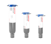
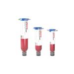
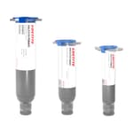
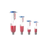
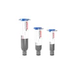
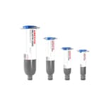
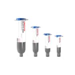
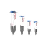
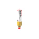
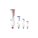
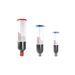
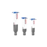
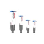
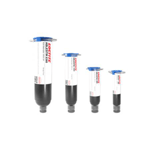
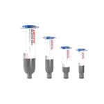
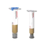
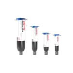
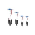
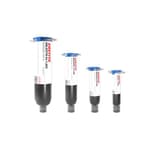
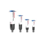
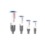
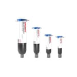
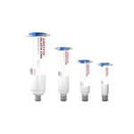
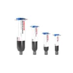
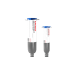
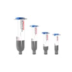
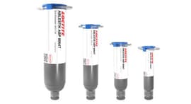
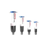
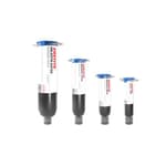
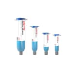
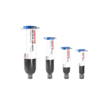
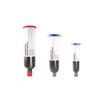
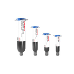
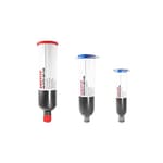
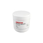
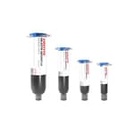
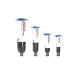
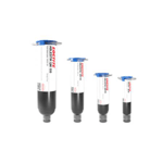
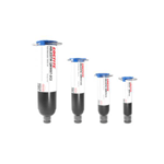
Die Attach Pastes
Our broad selection of die attach paste formulations provide the reliability and performance today’s leadframe and high-density laminate packages demand. Each package type – from BGAs to LGAs to Smart Cards – has different requirements, which is why we offer a suite of products that cater to the unique needs of those devices. Die attach pastes offer a low modulus for stress reduction and warpage elimination, as well as Bismaleimide (BMI) formulations for low moisture absorption to avoid package cracking during high temperature processing. Most of our semiconductor grade materials will pass the NASA outgassing standards if cured properly.
Process flexibility and superior performance underscore Henkel’s complete portfolio of die attach pastes for leadframe and laminate devices. Incorporated into applications such as automotive electronics, where temperature control and unfailing function are critical, LOCTITE ABLESTIK die attach pastes deliver high thermal conductivity and high reliability. Robust adhesion to various metal surfaces including palladium, copper, silver, gold and PPF along with proven low-bleed formulas make our die attach materials the products of choice for semiconductor packaging specialists.
LOCTITE ABLESTIK 8700E
- Electrically conductive
- Retains high shear strength after thermal cycling
- Thermally conductive
- 8 weeks
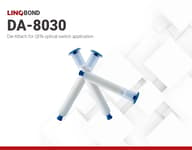
LINQBOND DA-8030 | Die-Attach
- Good electrical and thermal conductivity
- Excellent adhesion
- Outstanding manufacturability with low temperature cure
- 12 weeks
LOCTITE ABLESTIK 2025DNP
- Excellent dispense capabilities
- For mother die in array packaging
- 260ºC reflow capability for Pb-free applications
- In stock
LOCTITE ABLESTIK FS 849-TI
- Low outgassing
- Low electrical resistance
- High thermal conductivity - 7.8 W/mK
- 12 weeks
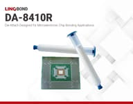
LINQBOND DA-8410R | Die-Attach
- Low resin bleed out
- excellent adhesion and reiliability
- Stencil printable
- 12 weeks
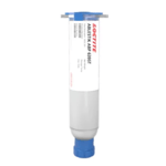
LOCTITE ABLESTIK ABP 6395T
- High reliability
- 30 W/(m-K) Thermal Conductivity
- Good adhesion to Ag, Cu, PPF, Non-BSM, and BSM die
- 12 weeks
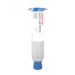
LOCTITE ABLESTIK ABP 6392TEA
- High electrical conductivity
- High thermal conductivity
- Good adhesion to a variety of substrates
- 2 weeks
LOCTITE ABLESTIK 958-7 | Electrically Conductive Adhesive
- Electrically conductive
- Good adhesion to gold
- Heat cure
- 8 weeks
LOCTITE ABP 2100ANP | PFAS-Free Die Attach Adhesive
- Formulated for Pb-free applications
- High hot/wet adhesion
- Excellent dispensability
- In stock
LOCTITE ABLESTIK ABP 2053SNP
- Formulated without intentionally added PFAS
- One-component
- Low stress
- In stock
LOCTITE ABLESTIK 2000
- Fast cure with no voids
- Minimal resin bleed
- Ultra low moisture absorption
- 12 weeks
LOCTITE ABLESTIK 84-1LMINB1
- Electrically conductive
- Long work life
- Bonds to difficult to wet surfaces
- 12 weeks
LOCTITE ABLESTIK 2000B
- Pb free applications
- High hot/wet adhesion
- Ultra low moisture absorption
- 12 weeks
LOCTITE ABLESTIK 2025D
- Excellent dispense capabilities
- For mother die in array packaging
- 260ºC reflow capability for Pb-free applications
- In stock
LOCTITE ABLESTIK 2600K
- Very Thermally conductive (20 W/mK)
- Good dispensability
- Low moisture absorption
- No longer available
LOCTITE ABLESTIK 2815A
- Very Thermally conductive (20 W/mK)
- Works well on Ag/Cu leadframes
- Low moisture absorption
- 8 weeks
Product Selector Guide
| Product | Filler | Viscosity (mPa·s) | Thixotropic index | Die size | Tensile modulus @25°C (N/mm2) | Glass transition temperature (°C) | CTE a1 (ppm/°C) | CTE a2 (ppm/°C) | Thermal conductivity (W/m.K) | Recommended cure |
|---|---|---|---|---|---|---|---|---|---|---|
| Loctite Ablestik 2030SC | Silver | 11600 | 4.6 | Small & Med | 3,300 | 29 | 45 | 130 | 2.3 | 90 sec. at 110°C |
| Loctite Ablestik 2030SCM | Silver | 14000 | 4.6 | Small & Med | 3,300 | - | - | - | 2.3 | 90 sec. at 110°C |
| Loctite Ablestik 2100A | Silver | 9,000 | 5.3 | Med & Large | 1,517 | 60 | 65 | 200 | 1.2 | 30 min. ramp and 15 min. hold at 175°C |
| Loctite Ablestik 2200D | Silver | 9,000 | 5.1 | Small & Med | 340 | -15 | 62 | 148 | 1 | 15-30min at 175°C |
| Loctite Ablestik 2600K | Silver | 9,000 | 3.5 | Small & Med | 3,700 | 68 | 36 | - | 20 | 30 min. ramp and 15 min. hold at 200°C |
| Loctite Ablestik 2815A | Silver | 8,000 | 5.6 | - | 5,700 | 63 | 64 | 122 | 20 | 30 min. ramp and 30 min. hold at 200°C |
| Loctite Ablestik 3230 | Silver | 9500 | 5.6 | Small & Med | 2,965 | 37 | 80 | 205 | 0.6 | 30 min. ramp and 15 min. hold at 175°C |
| Loctite Ablestik 71-1 | Silver | 14000 | 2.9 | Small & Med | 3,400 | 240 | 41 | - | 2 | 30 min. ramp at 150°C and 30 min. hold at 275°C |
| Loctite Ablestik 8175 | Silver | 55,000 | 2 | - | - | 90 | 55 | 200 | 3.2 | 30min at 150°C |
| Loctite Ablestik 8200C | Silver | 11500 | 5 | Small & Med | 4,621 | 190 | 60 | 130 | 1.2 | 30 min. ramp and 15 min. hold at 175°C |
| Loctite Ablestik 8290 | Silver | 16000 | 4 | Small & Med | 4,910 | 38 | 62 | 162 | 1.6 | 30 min. ramp and 15 min. hold at 175°C |
| Loctite Ablestik 8301 S1 | Silver | 10000 | 4.8 | Med | 540 | - | - | - | 0.9 | 60 sec. at 150°C |
| Loctite Ablestik 8302 | Silver | 10500 | 5 | Med & Large | 2,000 | 30 | 60 | 168 | 0.8 | 30 min. ramp and 60 min. hold at 175°C |
| Loctite Ablestik 8322A | Silver | 9000 | 4 | Med & Large | 1,600 | 30 | 65 | 135 | 0.7 | 30 min. at 175°C |
| Loctite Ablestik 8360 | Silver | 7,900 | 4.2 | - | 5,000 | 88 | 45 | 200 | 2.9 | 60min at 175°C |
| Loctite Ablestik 8361J | Silver | 9000 | 4.5 | Small & Med | 2,900 | 40 | 85 | 200 | - | 60min at 175°C |
| Loctite Ablestik 8370 | Gold | 13000 | 5.8 | Small | - | - | - | - | - | 60 min. at 150°C |
| Loctite Ablestik 8390 | Silver | 8700 | 3.1 | Small & Med | 4,650 | 73 | 60 | 135 | 1.8 | 80 sec. to peak 220°C (snap) |
| Loctite Ablestik 84-1LMI | Silver | 30000 | 4 | Small & Med | 9,254 | 103 | 55 | 150 | 2.4 | 60 min. at 150°C |
| Loctite Ablestik 84-1LMINB1 | Silver | 50000 | - | Small | - | 90 | 50 | 130 | 3.9 | 60min at 150°C |
| Loctite Ablestik 84-1LMIS | Silver | 17000 | 4 | Small & Med | 5,103 | 127 | 46 | 246 | 1.5 | 60 min. at 175°C |
| Loctite Ablestik 84-1LMISNB | Silver | 14000 | - | Small & Med | 5,000 | 115 | 54 | 190 | 3.5 | 60 min. at 175°C |
| Loctite Ablestik 84-1LMISR4 | Silver | 8000 | 5.6 | Small & Med | 3,900 | 120 | 40 | 150 | 2.5 | 1 hr. at 175°C |
| Loctite Ablestik 84-1LMIT | Silver | - | - | - | - | - | 52 | 200 | 4.3 | 60min at 150°C |
| Loctite Ablestik 84-1LMIT1 | Silver | 22,000 | - | - | 7,300 | 103 | 50 | 200 | 3.6 | 60min at 150°C |
| Loctite Ablestik 843-1 | Silver | 8500 | - | Small & Med | - | 76 | 49 | 120 | 2.07 | 30 min. at 170°C |
| Loctite Ablestik 849-TI | Silver | 9,500 | 5.2 | - | 7,802 | 211 | 44 | 155 | 7.8 | 15 minute ramp to 175°C + 30 minutes @ 175°C in N2 |
| Loctite Ablestik 8600 | Silver | 7500 | 4.7 | Small & Med | 9,600 | 187 | 46 | 160 | >4 | 60 sec. to peak 220°C (snap) |
| Loctite Ablestik 8700E | Silver | 18,000 | 3.0 | Small | 4,414 | 160 | 45 | 120 | 1.6 | 2 hours at 160°C |
| Loctite Ablestik 958-7 | Silver | 90,000 | - | - | - | 67 | 38 | 120 | 2.0 | 1 hour at 150°C |
| Loctite Ablestik 967-1 | Silver | 14,000 | - | Small | - | 110 | - | - | - | 2 hours at 80°C |
| Loctite Ablestik ABP 2030SCR | Silver | 15000 | 5 | Small & Med | 1,514 | 104 | 52 | 172 | 2 | 120 sec. at 120°C |
| Loctite Ablestik ABP 2032S | Silver | 11000 | - | Small & Med | 4,600 | 110 | 54 | 162 | 1 | 60 min. at 80°C |
| Loctite Ablestik ABP 6392TEA | Silver | 12500 | 5 | Small to Large | 4,738 | 56 | 63 | 190 | 9 | 30 minutes ramp to 175°C + 60 minutes @ 175°C, in air or N2 |
| Loctite Ablestik ABP 6395T | Silver | 8500 | 6.2 | Small to Large | 8,146 | 7 | 54 | 112 | 30 | 30 minute ramp to 200°C+30 minutes @200°C, in N2 or air |
| Loctite Ablestik ABP 8037TI | Silver | 11000 | 5.8 | Small | 5,900 | 46 | 62 | 94 | 4.1 | 30 min. ramp and 30 min. hold at 175°C |
| Loctite Ablestik ABP 8064T | Silver | 12000 | 5.8 | Med & Large | 8,620 | 44.5 | 47 | 136 | 22 | 60 min. ramp and 60 min. hold at 180°C |
| Loctite Ablestik ABP 8303A | Silver | 10500 | 4.6 | Small & Med | 1,800 | 30 | 70 | 180 | 1.5 | 30 min. ramp and 60 min. hold at 175°C |
| Loctite Ablestik JM7000 | Silver | 9000 | - | Small | 15,100 | 240 | 33 | - | 1.1 | 30 min. at 150°C |
| Loctite Ablestik QMI2569 | Silver | 35800 | 8 | Small, Med & Large | 2,190 | 250 | 16 | - | 60 | 10 min at 440°C (Depends on Die Size) |
| Loctite Ablestik QMI3555R | Silver | 35000 | 10 | Small, Med & Large | 11,500 | 150 | 16 | - | 80 | 10 min at 440°C (Depends on Die Size) |
| Loctite Ablestik QMI505MT | Silver | 12,000 | 4.8 | Large | - | -10 | 72 | 170 | 2.4 | 10sec at 200°C |
| Loctite Ablestik QMI516 | Silver | 8000 | 3 | Small & Med | 1.8 | 33 | 51 | 112 | 4.2 | 10sec at 150°C |
| Loctite Ablestik QMI516IE | Silver | 15,900 | 5.6 | Small & Med | 1,964 | 43 | 92 | 232 | - | 60sec at 90°C |
| Loctite Ablestik QMI519 | Silver | 9000 | 4.2 | Small & Med | 5,300 | 75 | 40 | 140 | 3.8 | >10 sec. at 200°C (SkipCure) |
| Loctite Ablestik QMI529HT | Silver | 18500 | 4.8 | Small & Med | 3,300 | 3.3 | 53 | 156 | 6.5 | 60 sec. at 185°C |
| Loctite Ablestik QMI529HT-LV | Silver | 16000 | 4 | Small & Med | 4,910 | 36 | 62 | 162 | 8 | 30 min. ramp and 60 min. hold at 175°C |
| Loctite Ablestik QMI529HT-2A1 | Silver | 18500 | 4.8 | Medium | 4,048 | 3.3 | 53 | 156 | 6 | 30min at 185°C |
| Loctite Ablestik QMI9507-2C2 | Silver | 18500 | 4.8 | Large | - | 3.3 | 53 | 156 | 6.5 | 30 min at 180°C |
| Loctite Ablestik SSP 2020 | Silver | 19000 | 5 | Small & Med | 12,490 | - | - | - | >100 | 10 min. ramp and 60 min. hold at 250°C (pressureless sintering) |
| Loctite Ablestik 2000 | Silver | 9,000 | 4.3 | Med & Large | 1,517 | 59 | 65 | 200 | 1.2 | 30 min. ramp and 15 min. hold at 175°C |
| Loctite Ablestik 2300 | Silver | 9,000 | 5.9 | Med & Large | 1,793 | 0 | 60 | 129 | 0.6 | 30 min. ramp and 15 min. hold at 175°C |
| Loctite Ablestik 2700HT | Silver | 10,000 | 5.5 | Small & Med | 4,740 | - | - | - | 11 | 30 min. ramp and 30 min. hold at 175°C in nitrogen |
| Loctite Ablestik 3290P | Silver | 12,000 | 3.5 | Small & Med | 2,900 | 136 | 68 | 101 | 0.8 | 180 sec. to peak 240°C (snap) |
| Loctite Ablestik 8200TI | Silver | 8,800 | 5.0 | Small | 11,300 | 220 | 76 | 205 | 3.5 | 180 sec. to peak 220 |
| Loctite Ablestik 8352L | Silver | 8,000 | 4.5 | Small/td> | 7,700 | 131 | 38 | 115 | 5.5 | 120 sec. to peak 220°C (snap) |
| Loctite Ablestik ABP 8060T | Silver | 12,000 | 6.0 | Small | 6,230 | 91 | 55 | 120 | 20 | 45 min. ramp and 60 min. hold at 200°C |
| Loctite Ablestik ABP 6392TEA | Silver | 12,500 | 4.0 | Med & Large | 4,450 | 51 | - | - | 9 | 30 min. ramp and 60 min. hold at 175°C |
| Loctite Ablestik ABP 8065T | Silver | 9,000 | 6.0 | Small | 5,180 | 48 | 40 | 146 | 10 | 30 min. ramp and 60 min. hold at 185 |
| Loctite Ablestik ABP 8066T | Silver | 10,000 | 6.0 | Small & Med | 4,824 | 67 | 53 | 90 | 15 | 30 min. ramp and 60 min. hold at 175°C |
| Loctite Ablestik FS 849-TI | Silver | 9,500 | 5.2 | Small | 7,802 | 211 | 44 | 155 | 7.8 | 15 min. ramp and 30 min. hold at 175°C |
| Loctite Eccobond 3185 | Silver | 42,000 | 4 | Medium | 290 | 37 | 55 | 135 | 3.9 | 60min at 175°C |
| LINQBOND DA-8030 | Silver | 20,700 | 3.5 | - | - | 92 | 57 | 147 | 4.5 | 60 minutes at 120°C |
Guidelines on Die Size
Small = 2mm and below
Med = 2mm x 2mm to 5mm x 5mm
Large = >5mm x 5mm
| Product | Filler (%) | Viscosity (mPa·s) | Thixotropic index | Die size | Tensile modulus @25°C (N/mm2) | Glass transition temperature (°C) | CTE a1 (ppm/°C) | CTE a2 (ppm/°C) | Thermal conductivity (W/m.K) | Recommended cure |
|---|---|---|---|---|---|---|---|---|---|---|
| Loctite Ablestik 2025D | Silica | 11,500 | 4.4 | Med & Large | 407 | 42 | 48 | 140 | 0.4 | 30 min. ramp and 15 min. hold at 175°C |
| Loctite Ablestik 2025DNP | Silica | 13,500 | 4.4 | - | - | 36 | 48 | 147 | 0.3 | 30 minutes ramp to 175°C + 15 minutes @175°C in N2 |
| Loctite Ablestik 2025DSI | Silica | 11,500 | 5 | - | 260 | -34 | 55 | 145 | 0.4 | 30 min. ramp and 15 min. hold at 175°C |
| Loctite Ablestik 2033SC | Silica | 11300 | 6.1 | Med | 2100 | 46 | 56 | 133 | - | 90 sec. at 110°C |
| Loctite Ablestik 2035SC | Silica | 11000 | 4.2 | Med | 2500 | 120 | 54 | 128 | 0.35 | 90 sec. at 110°C |
| Loctite Ablestik 2053S | Polymer | 13000 | 2.5 | Large | 87 | -21 | 149 | 216 | - | 30 min. and 15 min. hold at 175°C |
| Loctite Ablestik 6202C-X | Silica | 30000 | 2.5 | Large | 894 | 40 | 70 | 232 | 0.26 | 30 min. ramp and 60 min. hold at 90°C |
| Loctite Ablestik 798-3 | - | 36,500 | - | Small | - | 126 | 63 | 140 | 0.3 | 30min at 150°C |
| Loctite Ablestik 8-2 | - | - | - | - | - | 92 | 40 | 85 | 1.5 | 1.5 hours at 95°C |
| Loctite Ablestik 8006NS | Alumina/Silica | 55000 | 1.3 | Small & Med | 4376 | - | - | - | 0.44 | 120 min at 160°C |
| Loctite Ablestik 8387B | PTFE | 9500 | 4.5 | Med | 1400 | 96 | 94 | 165 | - | 120 sec. at 150°C |
| Loctite Ablestik 8387BS | PTFE/Silica | 14250 | 4.5 | Med | 1919 | 122 | 88 | 168 | - | 60 min. at 100°C |
| Loctite Ablestik 8388A | Silica | 8500 | 5.5 | Small & Med | 6600 | 117 | 31 | 187 | 0.47 | 300 sec. at 130°C |
| Loctite Ablestik 8700K | - | 45,000 | - | Small | - | 165 | 20 | 55 | 0.5 | 60min at 175°C |
| Loctite Ablestik 8900NCM | PTFE | 10000 | 6 | Med & Large | 680 | 44 | 72 | 118 | 0.3 | 30 min. ramp and 15 min. hold at 175°C |
| Loctite Ablestik 84-3 | Silica | 50000 | 14 | Small & Med | - | 85 | 40 | 100 | 0.8 | 60 min. at 150°C |
| Loctite Ablestik 84-3J | Silica | 20000 | 2.5 | Small & Med | 6,100 | 87 | 41 | 112 | 0.5 | 60 min. at 150°C |
| Loctite Ablestik 84-3LV | Silica | 12500 | 1.6 | Small & Med | - | 66 | 40 | 100 | 0.5 | 60 min. at 150°C |
| Loctite Ablestik 84-3MV | Silica | 29,000 | - | Medium | - | 70 | 40 | 110 | 0.5 | 60 min. at 150°C |
| Loctite Ablestik 968-2 | - | 45000 | - | Small & Med | - | 139 | 35 | 100 | 0.86 | 2 hours at 150°C |
| Loctite Ablestik ABP 2035SCR | Silica | 9830 | 4 | Med | 1500 | 118 | 50 | 135 | 1 | 120 sec. at 120°C |
| Loctite Ablestik ABP 6892 | fused silica 2% | 4100 | 1.75 | Med | 176 | -24.6 | 111.4 | 190.6 | ~0.3 -0.4 | 15 min. ramp and 30 min. hold at 130°C |
| Loctite Ablestik ABP 8035 | - | 7880 | - | Small | - | -56 | - | 268 | 0.2 | 60 min. at 150°C |
| Loctite Ablestik ABP 8142B | Silica | 12254 | 3.3 | Med & Large | 2,77 | -55.5 | - | 345 | - | 30 min. at 150°C |
| Loctite Ablestik ABP 8420 | Alumina | 13500 | 5.8 | Small & Med | 2850 | 75 | 54 | 154 | 0.3 | 30 min. ramp and 15 min. hold at 150°C |
| Loctite Ablestik ABP 8910T | Alumina | 13000 | 4.5 | Small | 8870 | 30 | 28 | 96 | 3.1 | 30 min. ramp and 15 min. hold at 175°C |
| Loctite Ablestik ABP 8920TC | Alumina | 16,000 | 6 | Medium | 8,580 | 49 | 19 | 54 | 3 | 30 min. ramp and 60 min. hold at 175°C |
| Loctite Ablestik 958-11 | - | 45,000 | - | Small | - | 89 | 15 | 45 | - | 2hours at 130°C |
| Loctite Ablestik DX20C | - | 12000 | - | Small | - | - | - | - | - | 60 min at 170°C |
| Loctite Ablestik QMI534 | PTFE | 9000 | 5 | Med & Large | 300 | -35 | 87 | 171 | 0.4 | >6 sec. at 240°C (SkipCure) |
| Loctite Ablestik QMI536 | PTFE | 20000 | 5.7 | Med & Large | 300 | -31 | 98 | 174 | 0.3 | >10 sec. at 150°C (SkipCure) |
| Loctite Ablestik QMI536HT | Boron Nitride | 13000 | 5.5 | Med & Large | - | 4 | 66 | 177 | 0.9 | 15 min. at 150°C (bondline) |
| Loctite Ablestik QMI536NB | PTFE | 10000 | 5 | Med & Large | 300 | -30 | 80 | 150 | 0.3 | 30 min. ramp 150°C |
| Loctite Ablestik QMI550 | Fluoropolymer | 11500 | 6.4 | Medium | - | -10 | 91 | 150 | 0.3 | 10 sec. at 150°C |
| Loctite Ablestik ABP 8611 | Alumina | 16000 | 3.8 | Small | 5000 | 82 | 71 | 148 | 0.7 | 30 min. ramp and 60 min. hold at 175°C |
| Loctite Eccobond 931-1T1N1 | - | 2,400 | 2.8 | Medium | - | - | - | - | - | 2 hours @ 100°C |
Guidelines on Die Size
Small = 2mm and below
Med = 2mm x 2mm to 5mm x 5mm
Large = >5mm x 5mm
Frequently Asked Questions
What are Thermoset materials?
The original die attach polymers were thermoset polymers and are still the most widely used today. After polymerization, these adhesives exhibit a rigid three-dimensional structure, a consequence of chemical bonds between adjacent chains (cross-linking). When heat is applied, these interlinked chains cannot move freely, hence their phase changes are not reversible.
The amount of interlinking between chains depends on the chemistry of thermoset polymers. High cross-linking means a hard, rigid and often brittle material, while low cross-linking means the material is more pliable and can be softened (they do not lose their original shape) by heating to high temperatures. Thermosets are commonly used in circuit board and semiconductor/device packaging for low to medium power applications. A disadvantage of thermosets is that sometimes, precise repeatability of the polymerization step can be difficult.
What are Thermoplastic die attach materials?
Thermoplastics were formulated to overcome the negative qualities of thermoset polymers. After polymerization, they are linear in structure. The manufacturer polymerizes the adhesive fully under controlled temperatures, reaction rates, times, and pressures. This ensures repeatable die attach properties.
Their linear structure allows them to be re-melted because their long polymer chains slide past one another on heating. Cooling the adhesive returns it to the solid state. As a die attach, a thermoplastic need not be fluid for effective bonding, the viscosity that allows the plastic to flow into the microstructure when pressure is applied should serve as a guide. The need for pressure also means additional equipment is required compared to thermosets. They are instrumental in circuit board device and packaging.
What happens to products after they expire? Can I use them?
Many die-attach materials are kept at -40C in order to keep the chemistry from advancing at high(er) temperatures. Even so, these materials (no matter whether they are cyanate esters or epoxies) do need to see higher temperatures (often > 150C) before the cure is ever initiated. So though the material may "age", the cure will not progress if it is kept at lower temperatures.
The first and most dramatic effect is the viscosity. Especially important in high volume production, if the viscosity changes over time, then the equipment settings may need to be continuously altered in order the continually dispense the same amount of material part after part. Furthermore, the CoA often states that the viscosity will remain within a specified range - so the shelf-life is implemented to protect the manufacturer beyond a known period that they have tested.
This said, the biggest risk is that it will not dispense as expected. If it does dispense fine, and you are able to dispense the material in such a way that you can mount a die, then (though - and I can\'t stress this enough - we do NOT guarantee it), you can use it with a high level of confidence that the material will act as expected once cured.
Should I worry about Silver migration in Conductive die attach?
Silver migration and dendritic silver formation underneath components between the two terminals is a known phenomenon in microelectronics. It can occur when metal structures (tracks, terminals, …) are subjected to a wet environment, with current passing through them and some acids to speed up the dissolution of the metals (or even quicker, their oxides which may have formed on the surface) in question.
In practice, however, this is something that does not happen too much in high reliability applications as most critical electronics are almost always shielded or protected by some form of encapsulation which eliminates most of the conditions mentioned before. In cheaper or unprotected setups though, this is something to keep in mind. Please also note that this is not only happening with silver adhesive, but actually can happen with all types of metal (Cu tracks, Sn terminations on components, etc.) including Ag containing solder. Even gold substrates in the right circumstances will be subject to this form of electrochemical migration and dendrite formation.
I have a freezer for X degrees. Can I keep my products there?
We do not have data on extensive storage at lower or greater temperatures than the ones indicated in the Technical data sheet. This is at the customer`s own risk. Therefore the properties can just be guaranteed for the particular temperature and time range indicated on the TDS. Those are the ones tested to be the best for the product.
How will my products be affected if they are not properly stored?
If stored below the recommended temperature, the product could crystallize, especially epoxies. Low temperatures could cause the formation of “Freeze-Thaw Voids” in the syringes. Any void formation can affect the dispensing characteristics of the adhesive, causing non-uniform dispensed volume.
Storage above the recommended temperature will decrease the shelf life but most likely will not change the chemistry or “destroy” the product (which could happen at lower temp). The same applies when you want to put a syringe back into the freezer, after using it. It is not recommended at all but the worst case scenario is to increase viscosity, decrease shelf life and maybe acquire some moisture causing voids.
It also depends on how long you plan to store it in an alternate temperature. But, to get the most out of the product we suggest to get a suitable freezer and to use the products as instructed in the TDS.
What is Oxygen inhibition?
In free-radically cured adhesives such as acrylates (Bismaleimides as well but not to the same extent), oxygen is known to inhibit polymerisation. In the bulk of the material, once the finite level of oxygen is depleted, the polymerisation process will initiate. This is more valid for certain UV and anaerobic cure materials, but typically not applicable for epoxy based materials (including semi-sintering) with “embedded hardener”.
At the adhesive fillet\'s surface, oxygen is continuously replenished by oxygen molecules in the atmosphere. The end result can lead to variations in cure and cured properties between the center of the die and the outer perimeter resulting in a tacky surface. Under Nitrogen, adhesives formulated with the secondary thermal cure initiator canbe thermally cured without prior exposure to light.
Why would I need a planetary mixer?
The whole idea with these mixers is both to maintain homogeneity of the die attach material and also to avoid air bubbles after a freeze-thaw process. Mixers such as THINKY and UNIX can help in streamlining the production process.
The air bubbles are caused by the thawing of the syringes and in extreme cases can actually pull in air from behind the plunger into the syringe. Air is generally not a disaster unless it is concentrated in "air bubbles" which would cause "voids" and "spitting" during a die attach dispense.
Is vacuum necessary when mixing the pastes?
The "vacuum option" is designed to also remove the air and prevent voids. In our experience, simply using a planetary mix without the vacuum option is plenty sufficient. The small air bubbles when mixed back in a homogenous paste are not seen again during die attach dispense and the vacuum option is an expensive and unnecessary luxury.
Can Ag-filled die attach pass automotive grade 0 on bare Cu?
Yes, recently Loctite Ablestik ABP6392TEA passed qualification for automotive grade 0 requirement die attach paste for PPF and bare Cu leadframes.
New formulations can pass AEC-100 Grade 0 on a wide die size range (2x2 up to 8x8mm). MSL1 /3 , temp cycling and HTS have been successful on QFN packages with MSL1 being possible on roughened Cu and MSL3 on rough/standard PPF and standard Cu.
What happens at the Tg of die attach?
At the Tg of a material 2 main things change. The Coefficient of Thermal Expansion (CTE) becomes larger, and the Modulus of the material becomes lower.
A higher CTE could result in a higher mismatch between different components and create more stress, while a lower modulus of the material allows for more stress absorption. This means that reliability within the application is a factor of multiple products, dimensions, and different stresses which tend to be "customer-specific" in the end.
Learn More
Conductive die attach pastes find the most significant application, about 80% of the die attach market, in attaching chips to leadframes where their electrical conductivity is an important parameter. These pastes are made of organic resins mixed with inorganic fillers. The resins could be thermosetting such as epoxy, phenolics, cyanate esters, and silicone or thermoplastics such as polyimides, and polyurethanes. Metal fillers such as silver, copper, gold, nickel, palladium have been used. The resin is responsible for the mechanical properties of the adhesive, and the fillers are responsible for its electrical and thermal conductivity. Conductive die attach pastes form electrical connections between leadframes, I/O leads, active and passive devices, and other circuit components. They also act as channels that facilitate electrostatic dissipation and electrical grounding.
Based on their electrical conductivity, conductive die attach pastes can be classified as:
- Isotropic conductive adhesives (ICAs), popular for surface mount technology. They conduct electricity in all directions equally.
- Anisotropic conductive adhesives (ACA) used for adhering IC chips to glass panels in LCDs and in tape automated bonding packages. They conduct electricity in the Z-axis only.
- Non-conductive adhesives (NCAs) are useful in applications where the mechanical bond from the die attach is more important than its electrical conductivity.
A consequence of chips and devices becoming smaller is that they are susceptible to high temperatures experienced during electrical transmission. Without sufficient heat dissipation from a die attach material to appropriate heat sinks in a circuit, destruction and failure of parts become inevitable. Thermal conductivity is, therefore, a critical parameter affecting performance. For a paste to qualify as electrically conductive, its minimum thermal conductivity as specified by Method 5011 of the MILD-STD-883 standard is 1.5 W/m·K.
Properties of Conductive Die Attach Pastes Affecting Their Performance
Numerous conductive die attach pastes are available in the market, each with its unique differentiating property. The essential properties to consider that have far-reaching effects on the performance of any given product are: filler composition, morphology, manufacturing, and processing requirements.

Type of Filler and Thermal Conductivity
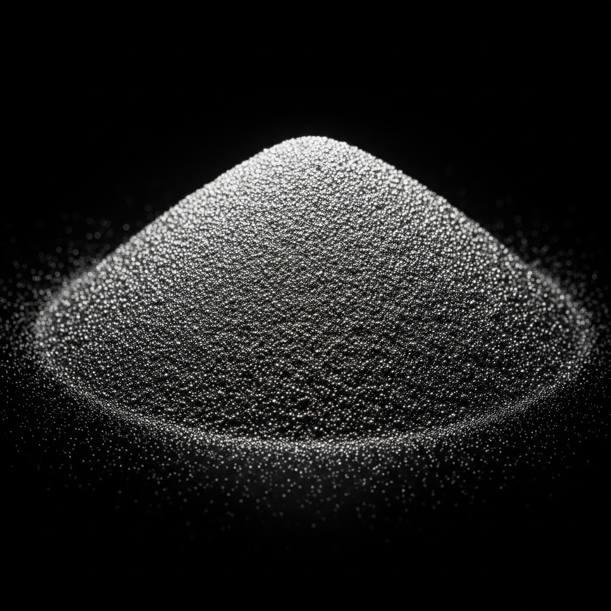
The majority of polymer resin used in formulating conductive die attach are insulators by nature, so fillers are incorporated to increase their electrical and thermal conductivity. Fillers that have been used commercially are silver (429 W/m·K), copper (401 W/m·K), gold (318 W/m·K), and nickel (90-92 W/m·K). Their thermal conductivity values indicate why silver is so popular.
Understandably, silver-filled die attach pastes are expensive. However, silver exhibits other superior qualities including the fact that silver oxide is stable and conductive. On the other hand, copper-filled variants experience a decrease in conductivity with oxide growth after exposure to high temperatures. Nickel has a low oxidation rate, and given its lower thermal conductivity value, is a preferred filler in low-cost anisotropic adhesives.
Even though the thermal conductivity values of the filler metals are substantial, those of the formulated pastes are considerably lower. A value such as 1.9 W/m·K is not unusual for commercially available silver-filled pastes, while others as high as 7-11 W/m·K are also available.

Percentage of Filler
The filler percentage of a composite mixture is important because of the underlying trade-offs. A large amount of metal is necessary for greater conduction, but this affects physical properties like elasticity and mechanical strength.
According to percolation theory, a critical filler concentration exists where the 3-D network structure is established, and the increase in conductivity becomes significant by several orders of magnitude. Beyond this concentration, conductivity does not increase as noticeably with an increase in filler composition. Therefore, only a minimum quantity of filler is required to achieve a degree of electrical performance that is inherent to the composite. Typical values for ICAs lie between 25-30 vol % and 5-10 vol % for ACAs.
Tensile Modulus and CTE
More than connecting materials together, adhesives act as load distributors. Assembled packages having different CTEs need a low modulus adhesive to compensate for the mismatch. Increasing the filler loading for the sake of high conductivity increases the tensile modulus of a die attach paste but decreases the ultimate strength. This could result in cracking during thermal cycling or vibration. Manufacturers use plasticizers to lower the modulus and add flexibility.
Filler Morphology
The characteristics of the filler material such as size, shape, orientation, and distribution in the mixture affect the viscosity/rheology of the formulation. These properties come into play in the bond line thickness. Since thin bond lines enhance thermal conductivity, fine particle sizes are preferable and it’s why metal powders with diameter sizes between 5-20 µm are typical.
Processing Requirements
Parameters like temperature, cure time, pressure, storage conditions, and shelf life, impact not only the strength and reliability of a die bond, but also design and manufacturing decisions.
Manufacturing
In addition to the resin and filler, other components like hardeners, thinners and curing agents are added to modify cure rates, viscosity, and other mixtures properties. The die attach paste can be supplied as a single component where the catalyst is latent (usually by storing below -40°C ) until exposed to the given cure temperature. Supplied as two components, you get a separate resin, called part A, and the catalyst, part B. Either or both part A and B may contain the metal filler. The parts are weighed, mixed, degassed and cured. Cost-cutting objectives favor formulations that are solvent-free and have shorter cure cycles.
Curing
Curing involves the polymerization of the resins to solidify them into strong adhesive joints. Curing agents and sufficient heat (oven, UV) are often required for the reaction to occur and the type of catalyst will influence the cure time and temperature.
Typical pastes cure anywhere between 80°C to 180°C and some two-component die attach can cure at room temperature. Snap cure (often one-component) pastes derived from modified cyanate esters can cure in under 1-2 minutes making them an excellent choice for high volume manufacturing.
Storage
One-component formulations often need to be stored in a freezer, and this reduces the ease of using it. If stored incorrectly, adhesives can polymerize prematurely, absorb moisture, or crystallize. Also, if left too long before dispensing at room temperature, an adhesive mixture can separate leading to die bond inconsistencies where some parts are resin-rich and will flow excessively, while other parts are filler-rich and don’t flow easily. Die attach formulations based on bismaleimide resins were developed to counteract the tendency to absorb moisture.
Dispensing
Conductive (and non-conductive) die attach pastes may be syringe dispensed or stencil printed depending on the viscosity of the mixture.
Applications of Conductive Die Attach Pastes
- Isotropic conductive adhesives (ICAs), popular for surface mount technology. They conduct electricity in all directions equally.
- Anisotropic conductive adhesives (ACA) used for adhering IC chips to glass panels in LCDs and in tape automated bonding packages. They conduct electricity in the Z-axis only.
- Non-conductive adhesives (NCAs) are useful in applications where the mechanical bond from the die attach is more important than its electrical conductivity.
Except for the difference in their composition and application, non-conductive die attach pastes are not far off from their conductive cousins. They are made of organic resins like epoxy, polyimides, silicones, acrylates and non-conductive fillers that could be metal, metal oxides, metal nitrides and more. Examples of ceramic and inorganic fillers are silica (SiO2), alumina (Al2O3), and beryllium oxide (BeO). An organic filler like PTFE has also been used successfully.
These pastes find the most use in die attach for semiconductors and surface mount devices, where a strong adhesion that can withstand physical and thermal stresses combined with strong electrical insulation is the priority. Example applications are automotives, sensors, consumer electronics, memory cards, RFID cards, USBs and LEDs.
There are applications where pastes with low thermal and electrical conductivity are sufficient. There are other situations, however, where pastes need high thermal conductivity because temperature control is critical. This second category are thermally conductive and electrically insulating die attach pastes. Unfilled polymer resins are natural thermal insulators (0.1–0.5 W/m·K), and the added fillers increase thermal conductivity tenfold or better. Method 5011 of MIL-STD-883 standard specifies the minimum thermal conductivity for electrically insulative die attach as 0.15 W/m·K.
.jpg)
Properties of Non-Conductive Die Attach Pastes Affecting Their Performance
.png)
Thermal Conductivity and Heat Dissipation
The thermal conductivity of silver-filled die attach pastes makes it excellent for heat dissipation, but in electronic applications where a high thermal conductivity must be combined with low electrical conductivity, ceramic fillers such as alumina and silica are good alternatives. Examples are packaging materials for power semiconductor devices where the heat generated needs to be dissipated to ensure its long life and reliability.
Thermal dissipation through the die attach occurs mainly through conduction and convection. Therefore, the morphology of the filler materials, their shapes, sizes and their distribution in the resin influence the process. Smooth ceramic powders less than 20 µm in diameter are typical.
Thermal Conductivity and Type of Non-Conductive Filler
The thermal conductivity of diamond is impressive, as high as 1500-2000 W/m·K depending on its purity, and that of diamond-filled pastes can exceed 12 W/m·K. However, the price of diamond is prohibitive for everyday applications. Fillers that have found commercial use are alumina (99%, 40 W/m·K), aluminum nitride (170-260 W/m·K), boron nitride (130-260 W/m·K), and silicon carbide (270 W/m·K).
Mechanical Strength and Coefficient of Thermal Expansion
The resin part of the paste is responsible for providing shear and tensile strength to the adhesion throughout all the possible conditions an assembly will encounter. Apart from thermal conductivity and flow properties, the type of filler used influences the CTE of the paste which is critical when bonding dissimilar materials together. Unfortunately, while these fillers may improve the CTE, their addition negatively impacts the bond strength. It becomes a trade-off decision about what the percentage of filler loading should be for an application.
Processing and Dispensing
Non-conductive pastes may be based on thermoset or thermoplastic resins. The paste can be supplied as a single component with a latent catalyst/ hardener or a two-component mixture, requiring expert weighing, mixing and degassing of the resulting composite.
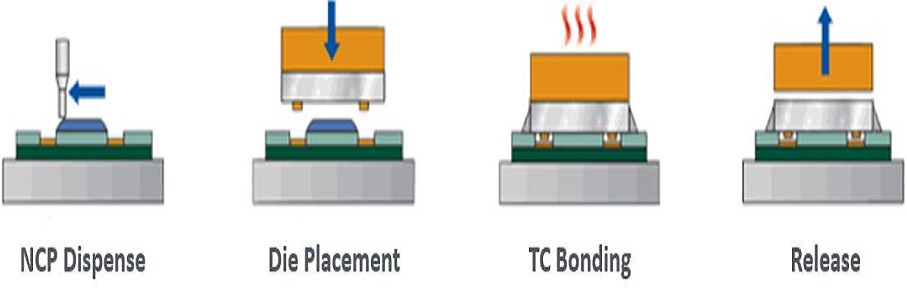
Die attach pastes (conductive and non-conductive) can be deposited into any shape through syringe dispensing or stencil printing, making them ideal, where the components to be bonded, have interesting geometries. They can also be scaled for mass manufacturing and automation using high-end equipment that is optimized for all the critical parameters to avoid common defects such as voiding and bond thickness variation.
Percentage of Filler and Flow Properties
Boron nitride at a loading level of 40 wt% can produce a mixture with a bulk thermal conductivity of 8-10 W/m·K, although the thixotropic end result can be difficult to dispense. On the other hand, alumina is low cost and a popular choice due to its more manageable flow properties. When mixed with organic resin, the resulting paste has a thermal conductivity of 1.5 W/m·K at a loading level of 75 wt%.
Therefore, although the thermal conductivity of a paste may be increased by adding more filler as far as the density of the resin will allow (typically, 85%–90% by weight and 40%–50% by volume), there is a point where doing so is no longer beneficial, negatively impacting other properties of the paste, e.g., viscosity. To counter this, thixotropic additives are introduced to improve flow properties. You will find that many commercially available die attach pastes are formulated using similar core resins, fillers, and catalysts but differ in the quantities of these ingredients.
Another factor affecting the thermal conductivity of a paste other than type and percentage of filler is the curing requirement of the paste.
Electrical Insulation
Dissipation Factor
It measures the power loss in a material experiencing an alternating electric field, a ratio of the power dissipated to the power applied. A low value implies the die attach paste, the substrates to which it adheres, and the surrounding circuit components will experience only low levels of heating. At ambient temperatures, typical DF values lie between 0.003 to 0.030 at 1 KHz, and can go up to 0.050 at 1 MHz.
Dielectric Constant
A dimensionless ratio that measures the ability of a material to store electrical energy when exposed to an electric field. The dielectric constant for non-conductive die attach pastes used for electrical insulation will typically lie between 2-5. A higher value in the range 6-12 is acceptable where some electrical conductivity can be overlooked.
Dielectric Strength
It measures the maximum voltage that, when applied across a material, won’t cause dielectric breakdown. Beyond this point (breakdown voltage), a non-conductive die attach paste becomes electrically conductive. Also, dielectric strength decreases as temperature or frequency increases.
Applications of Non-Conductive Die Attach Pastes
- Leadframe packaging for proper attachment to surfaces like copper, gold, silver, palladium, PPF
- Laminate packaging in BGAs, LGAs
- Printable board on chip for DRAM devices, flexible circuit boards
- For bonding high power LEDs and surface mounted devices, SMDs to PCBs
- For bonding ICs to heat sinks
Related Blogs

Optimizing Die Attach Epoxies
This blog discusses how die attach epoxy application can be optimized for a smoother and more efficient production.


