
Solder pastes
Best-in-class thermal performance, flexibility, reflow and reliability
-
Home

-
Products
-
Soldering Materials
- Solder Pastes
Solder Pastes
Solder paste is a mixture of powdered solder and a flux, used in surface mount technology (SMT) to create electrical connections between components and a printed circuit board (PCB). The flux helps to clean and protect the metal surfaces during soldering, while the solder powder melts and creates a bond between the components and the board. It is applied on a PCB with the help of a stencil or a foil. The stencil accurately deposits the right amount of paste on the surface mount pads. It should be properly aligned on the circuit board. Solder paste application is one of the most important aspects of component mount process in PCB assembly.
At Caplinq, we understand the importance of reliable electrical connections in today's demanding electronics landscape. That's why we're proud to offer a comprehensive selection of best-in-class solder pastes, meticulously formulated to deliver exceptional performance and unwavering reliability. Solder paste is the cornerstone of surface mount technology (SMT), creating the critical electrical and mechanical connections between electronic components and printed circuit boards (PCBs).
Experience optimal printability with our precisely formulated pastes, featuring tailored viscosities and particle sizes for consistent, high-definition deposits. Achieve robust and reliable solder joints with our pastes' exceptional wetting characteristics, ensuring maximum contact area and electrical conductivity. Benefit from long-lasting performance with our high-quality alloys and advanced flux technology, delivering resilience in even the most demanding applications. Enjoy streamlined processes with our diverse range of solder paste options, including no-clean and clean formulations to optimize your production efficiency. Ready to elevate your SMT experience? Explore Caplinq's range of best-in-class solder pastes and discover the difference that comes with partnering with an adhesive expert.
-


LINQALLOY SP-Bi57Sn42Ag1 | Solder paste
- Sn42Bi57Ag1 Alloy
- 138°C Eutectic
- Powder size: T3 (25-45um) and T4 (20-38um)
- 12 weeks
-

LINQALLOY SP-SAC105 | Solder paste
- Pb-free Sn98.5–Ag1–Cu0.5 alloy
- Solder paste for surface mount technology
- RoHS compliant
- 8 weeks
-

LINQALLOY SP-PSA525 | No Clean Solder Paste
- Superior wetting
- Reliable clog-free dispensing
- High thermal fatigue resistance for power semiconductor applications
- 12 weeks
-


ALPHA CVP-390V Solder Paste
- Superior electrochemical reliability
- Wide process window
- Reliable post reflows flux residue
- 4 weeks
-

ALPHA OM340 Solder Paste
- Available in different alloys
- Maximizes reflow yield for Pb-free processing
- Excellent print consistency
- 8 weeks
-

ALPHA OM-535
- Enables elimination of a second or third reflow cycle
- 8+ Hour stencil life
- Compatible with all commonly used Pb-free surface finishes
- 3 weeks
-

KESTER EP256 Solder Paste
- Stable wetting behavior
- Excellent printing characteristics
- High activity on all substrates
- 3 weeks
-

KESTER EM808 Solder Paste
- Excellent solderability
- Print speed up to 150 mm/sec
- Excellent anti-slumping features
- 3 weeks
-

-

KESTER HM531
- Excellent anti-slump characteristics
- Minimal voiding under BGA components
- Great solderability
- 3 weeks
-

-

-

KESTER NP505-HR Solder Paste
- High reliability
- Exceptional print performance
- Zero-halogen formula
- 3 weeks
-

ALPHA CVP-390
- Long stencil life
- Wide reflow profile window
- Excellent coalescence and wetting performance
- 3 weeks
-

ALPHA OM550 Solder Paste
- Low reflow peak temperature
- Reduction of warpage up to 99%
- Long stencil life
- 3 weeks
-

-

LINQALLOY SP-SAC307 | Solder paste
- Sn99Ag0.3Cu0.7 Alloy
- 217 - 228°C
- Powder size: T3, T4 and T5
- 8 weeks
-

LOCTITE HF 250DP
- 95.5%Sn: 3.8%Ag:0.7%Cu - 96SC Alloy
- Lead free Soldering
- Suitable for reflow in nitrogen
- 12 weeks
-


LOCTITE DA 100
- Sn91.5/Sb8.5 - Pb free 92A Alloy
- Semiconductor die attach
- Excellent dispense capabilities
-
No longer available
-

-

-

-

-


Product Selector Guide
| Product | Description | Alloy | Particle size distribution | Viscosity (mPA.s) | Melting temperature | Shelf life |
|---|---|---|---|---|---|---|
| Dispensable | ||||||
| DA 100 | Tin antimony, dispense solder paste for Die attach | 92A | Type 4 | 300,000 | 242°C | 12 months at -20°C |
| GC 50 | Room temp stable, Jet dispensable and fine particle paste for small components | SAC305 | Type 5 | 110,000 | 217°C | 180 days in RT |
| Printable | ||||||
| Loctite GC 10 | Room temp stable, Multi purpose solder paste for PCB assembly | SAC305 | Type 3, 4, 5 | 200,000 | 217°C | 12 months in RT |
| Loctite GC 18 | Room temp stable, low voiding paste for large area components such as QFN with heat sink. | SAC305 | Type 4 | 250,000 | 217°C | 180 days in RT |
| Loctite HF 212 | Refrigerated, Halogen-free, solder paste for PCB assembly | 90iSC 97SC |
Type 4 | 175,000 | 205 - 218°C | 180 days at 0°C - 10°C |
| Loctite LF 318 | Refrigerated, High reliability solder paste for PCB assembly. Both printable and dispensable versions. | 90iSC | Type 3 | 650,000 | 205 - 218°C | 180 days at 0°C - 10°C |
| Product | Description | Alloy | Particle size distribution | Viscosity (mPA.s) | Melting temperature | Shelf life |
|---|---|---|---|---|---|---|
| LINQALLOY Sn42Bi57Ag1 | Low eutectic solder paste for LED Assembly | Sn42Bi57Ag1 | Type 3, 4 | - | 138°C | 6 months at 5°C |
| LINQALLOY SP-SAC105 | Pb-free solder paste designed for Surface Mount Technology (SMT) | SAC105 | Type 3, 4, 5 | 200 | 223°C | 6 months at 5°C |
| LINQALLOY SP-PSA525 | High lead solder paste designed for clog-free dispensing die attach processes | Pb92.5Sn5Ag2.5 | Type 3, 4, 5 | 130 - 170 | 287°C | 6 months at 5°C |
| LINQALLOY SP-SAC305 | Pb-free solder paste designed for Surface Mount Technology (SMT) | SAC305 | Type 3, 4 | 160 - 230 | 217°C | 6 months at 5°C |
| LINQALLOY SP-SAC307 | Pb-free solder paste designed for Surface Mount Technology (SMT) | SAC307 | Type 3, 4, 5 | 190 - 230 | 220°C | 6 months at 5°C |
▶ Macdermid Alpha Solder Paste Selection Guide (Click here to expand)
| Product | Alloy Type | Flux Type | Halogen Content | Flux Classification | Shelf Life (months) | Stencil Life (Hours) | Alloy | Features |
| Kester EP256HA | Leaded | No-Clean | Halogenated | ROL1 | 6 | 8+ | Sn63Pb37, Sn62Pb36Ag2, Sn43Pb43Bi14 | Excellent Printing, wide process window, high flux activity |
| Kester EP256 | Leaded | No-Clean | Halogenated | ROL1 | 6 | 8+ | Sn63Pb37, Sn62Pb36Ag2 and Sn43Pb43Bi14 | Excellent Printing, wide process window |
| Kester NXG1 (Leaded) | Leaded | No-Clean | Halogenated | ROL1 | 8 | >8 | Sn63Pb37 | Premium leaded, next gen reliable shiny fine pitch printing |
| Kester R276 (Leaded) | Leaded | No-Clean | Zero-Halogen | ROL0 | 6 | 8+ | Sn63Pb37, Sn96.5Ag3Cu0.5, Sn43Pb43Bi14, Sn10Pb88Ag2, Sn95.5Ag3.8Cu0.7, Sn62Pb36Ag2 | Excellent dispensing, leaded |
| Kester FL250D | Leaded | No-Clean | Zero-Halogen | ROL0 | 4 | 8+ | Sn63Pb37, Sn62Pb36Ag2 | Automotive grave, easy post-soldering process chemicals |
| NP545 (Leaded) | Leaded | No-Clean | Zero-Halogen | ROL0 | 12 | 8+ | SAC305 | High shelf life, reliable fine‑pitch printing |
| Alpha OM-5100 | Leaded | No-Clean | Zero-Halogen | ROL0 | 6 | >8 | Sn63Pb37, Sn62Pb36Ag2, Sn95.5Ag3.8Cu0.7, Sn62.8Pb36.8Ag0.4 | Universal Tin-Lead, Wide Process Window |
| Alpha OM-5300 | Leaded | No-Clean | Zero-Halogen | ROL0 | 6 | >8 | Sn63Pb37, Sn62Pb36Ag2, Sn62.8Pb36.8Ag0.4 | Universal Tin-Lead Solder Paste |
| Kester R231 | Leaded | Rosin | Halogenated | ROL0 | 4 | 8 | Sn63Pb37, Sn62Pb36Ag2 | RMA solder Paste for long Stencil/Print life |
| Kester R276 (Lead-Free) | Leaded | Water-Soluble | Halogenated | ROL0 | 6 | 8+ | Sn63Pb37, Sn96.5Ag3Cu0.5, Sn43Pb43Bi14, Sn10Pb88Ag2, Sn95.5Ag3.8Cu0.7, Sn62Pb36Ag2 | Excellent dispensing, lead-free |
| Kester R500 (Leaded) | Leaded | Water-Soluble | Halogenated | ORM0 | 6 | 8 | Sn63Pb37 | Leaded, consistent dot dispensing, high flux activity |
| Kester R560 | Leaded | Water-Soluble | Zero-Halogen | ORH0 | 6 | 8 | Sn63Pb37, Sn62Pb36Ag2 | Low Voiding (<5%) and good Metallization, high temperature/humidity resistance |
| Kester R562 | Leaded | Water-Soluble | Zero-Halogen | ORM0 | 6 | 12 | Sn63Pb37, Sn62Pb36Ag2 | Low Voiding (<3%) and good Metallization, high temperature/humidity resistance |
| Kester HM531 | Leaded | Water-Soluble | Zero-Halogen | ORM0 | 6 | 8+ | SnP63Pb37, Sn62Pb36Ag2 | Excellent Printing, long Stencil/Print life, High Manufacturability and Metallization (wetting) |
| Kester NXG1 (Lead-Free) | Lead-Free | No-Clean | Halogenated | ROL1 | 8 | >8 | SAC305 | Premium, next Gen reliable shiny fine pitch printing |
| Kester EM907 | Lead-Free | No-Clean | Halogenated | ROL1 | 4 | 12+ | SAC305, Sn96.5Ag3.5 | Halogenated, lead-free paste joint similar to SnPb performance |
| Kester NP545 (Lead-Free) | Lead-Free | No-Clean | Zero-Halogen | ROL0 | 12 | 8+ | SAC305 | NXG, general high‑performance, versatile, long shelf life |
| Kester EM918 | Lead-Free | No-Clean | Halogenated | ROL0 | 6 | >8 | SAC305, Sn96.5Ag3.5 | Non-halogenated, lead-free, similar to SnPb performance, wider processing window |
| Kester NP575-KAP | Lead-Free | No-Clean | Zero-Halogen | ROL0 | 6 | >8 | SAC305 | NXG, maximum flexibility & reliability futomotive, aerospace, or demanding environments |
| Kester NP505-HR | Lead-Free | No-Clean | Zero-Halogen | ROL0 | 12 | 8 | SAC305 | NXG, High reliability, Harsh environments for residue reliability and low voiding |
| Kester NP505-LT | Lead-Free | No-Clean | Zero-Halogen | ROL0 | 6 | 12 | SAC305, Sn42Bi57Ag1 | NXG, low temperature reflow, for temp. sensitive substrate or component |
| Kester NP510-LT-HR-L1 | Lead-Free | No-Clean | Zero-Halogen | ROL0 | 6 | 8 | HRL1 | NXG, low temperature reflow, High reliability |
| Kester EM919G | Lead-Free | No-Clean | Zero-Halogen | ROL0 | 6 | 12+ | SAC305 | NXG, longer shelf life for high volume manufacturing and ultra fine pitch |
| Kester NP560 | Lead-Free | No-Clean | Zero-Halogen | ROM0 | 6 | 8 | SAC305 | Ultra‑low voiding under QFNs, reliable fine‑pitch printing |
| Alpha JP-500 | Lead-Free | No-Clean | Zero-Halogen | ROL0 | 6 | NA | SAC305, SAC405 | Jetting Solder Paste |
| Alpha JP-501 | Lead-Free | No-Clean | Zero-Halogen | ROL0 | 6 | NA | Sn42Bi57.6Ag4 | Jetting Solder Paste, Low melting point alloy |
| Alpha OM-340 | Lead-Free | No-Clean | Zero-Halogen | ROL0 | 6 | 8 | SAC305, SAC405, Sn96Ag4, SACX® Plus 0307, SACXPlus 0807, Innolot |
Increased Spread Wetting, High Reliability, Low HIP |
| Alpha CVP-390 | Lead-Free | No-Clean | Zero-Halogen | ROL0 | 6 | >8 | SAC305, SACX Plus™0307, SACX Plus™ 0807, InnoLot™ | High reliable fine‑pitch printing, High Soak Profile, Paste in Through Hole |
| Alpha CVP-390V | Lead-Free | No-Clean | Zero-Halogen | ROL0 | 6 | >8 | SAC305 and Innolot alloys | Higher reliable fine‑pitch printing, High Soak Profile, Paste in Through Hole |
| Alpha CVP-520 | Lead-Free | No-Clean | Zero-Halogen | ORH0 | 4 | >8 | SAC305 | Low melting point alloy, Excellent paste in through hole performance, for PV Applications |
| Alpha OM-353 | Lead-Free | No-Clean | Zero-Halogen | ROL0 | 6 mo | >8 | SAC305, SACX Plus 0307, InnoLLot | Enabling Ultra-Fine Feature Printing |
| Alpha OM-535 | Lead-Free | No-Clean | Zero-Halogen | ROL0 | 6 mo | >8 | SBX02, SnBi0.4Ag, 42Sn57Bi1Ag | Low Melting Point, High Mechanical Strength and Drop Shock Performance for PV Applications |
| Alpha OM-362 | Lead-Free | No-Clean | Zero-Halogen | ROL0 | 4 | 8 | SAC305, Innolot | High Reliability, Ultra Low Voiding |
| Alpha OM-100 SnCX07 | Lead-Free | No-Clean | Zero-Halogen | ROL0 | 6 | 16 | SnCX07 | Lower cost than SAC base, reliable fine‑pitch printing and thermal cycling |
| Alpha OM-565 HRL3 | Lead-Free | No-Clean | Zero-Halogen | ROL0 | 6 | 8 | HRL3 | High Reliability, outperforms SAC305 in thermal cycling and mechanical strain |
| Kester EM808 | Lead-Free | Water-Soluble | Halogenated | ORH1 | 6 | 8+ | SAC305, Sn96Ag4 | Prints consistently, wets aggressively |
| Kester EM828 | Lead-Free | Water-Soluble | Halogenated | ORH1 | 6 | >8 | SAC305 | Low-voiding, prints consistently, wets aggressively |
| Kester R500 (Lead-Free) | Lead-Free | Water-Soluble | Zero-Halogen | ORM0 | 6 | 8 | SAC305 | Consistent dot dispensing, high flux activity |
| Kester R520A | Lead-Free | Water-Soluble | Zero-Halogen | ORH0 | 4 | >8 | SAC305 | High flux activity for excellent wetting, fine‑pitch printing |
| Kester WP616 | Lead-Free | Water-Soluble | Zero-Halogen | ORM0 | 6 | 8+ | SAC305 | High Reliability, excellent Printing |
| Alpha WS-826 | Lead-Free | Water-Soluble | Zero-Halogen | ORM0 | 6 | 8 | SAC305 | Excellent Cleanability, stencil life, reliable under high humidity and temperature |
Frequently Asked Questions
Frequently asked questions about Soldering Materials
What is Solder Paste Reflow?
Solder paste reflow is the process of heating the PCB with the applied solder paste to melt the solder and create electrical connections between the components and the PCB. The reflow profile, which includes the temperature ramp-up, dwell time, and cooling rate, is crucial for achieving good solder joint quality.
What is the difference between IR reflow and conventional reflow?
Both conventional oven reflow and infrared (IR) reflow are common methods for soldering surface mount components (SMCs) to printed circuit boards (PCBs). Conventional ovens use hot air to heat the board, while IR reflow uses infrared radiation. Conventional ovens are cheaper, widely available, and suitable for various PCB sizes and component densities, but they can be slower and have uneven heating. IR reflow offers faster heating, more uniform temperatures, and less thermal shock to components, but it's generally more expensive.
What is Solder Paste Printing?
Solder paste printing is the process of applying solder paste to a PCB using a stencil and a squeegee. The squeegee applies pressure to the paste, forcing it through the openings in the stencil onto the PCB pads. The stencil's thickness and the openings' size and shape are critical factors in achieving consistent and precise solder paste placement. The printing process is critical for achieving consistent and accurate solder paste placement.
What is the Role of Flux Activity in Solder Paste?
Flux activity refers to the chemical reactivity of the flux in the paste. A more active flux can clean surfaces more effectively but may also be more corrosive. The choice of flux activity depends on the specific application and the materials being soldered.
Do the flux residue need to be removed?
The need to remove flux residue after an SMT process depends on the type of flux used.
-
No-clean flux: These fluxes are designed to leave a non-corrosive residue that does not require cleaning. They are often preferred in applications where cleaning can be time-consuming or introduce contamination risks.
-
Water-soluble flux: These fluxes require cleaning with water or a water-based cleaning solution to remove the residue. They are often used when the residue could potentially cause corrosion or interfere with subsequent processes.
-
Solvent-soluble flux: These fluxes require cleaning with a solvent-based cleaning solution. They are less commonly used due to environmental concerns and the potential for solvent residues to remain on the PCB.
How Does Particle Size Affect Solder Paste?
Particle size refers to the average diameter of the solder powder particles in the paste. Smaller particles can provide finer detail and better wetting, but they may also be more susceptible to oxidation and require more careful handling. Larger particles, on the other hand, can be easier to handle but may not provide the same level of detail.
What is the Viscosity of Solder Paste?
Viscosity measures the resistance of a fluid to flow. In solder paste, it's a crucial property that affects how the paste spreads and flows during application through the stencil apertures. Higher viscosity pastes are thicker and may require more pressure to apply, while lower viscosity pastes are thinner and flow more easily. The viscosity range of printing solder paste is about 100-200Pa.s, which is required to adjust for different scenarios.
What is Solder Paste Inspection (SPI)?
Solder paste inspection is the process of examining the applied solder paste for defects such as voids, bridging, and insufficient volume. Visual inspection and automated optical inspection (AOI) are common methods for solder paste inspection. Refer to the full PCB Assembly Process Flow to understand more about the solder paste inspection.
How Does Solder Paste Temperature Affect Solder Joint Quality?
The temperature at which the solder paste is reflowed is critical for achieving good solder joint quality. If the temperature is too low, the solder may not melt completely, resulting in weak or incomplete joints. If the temperature is too high, the solder may become overly fluid, leading to excessive wetting or bridging.
Learn More
Solder Paste Classification
By Solder Paste Particle Size
Particle size plays a pivotal role in solder paste performance, affecting print resolution, wetting efficiency, and process reliability. Finer powders support high-density, fine-pitch applications but are more susceptible to oxidation, while coarser powders enhance process robustness at the expense of print precision. The appropriate particle size is determined by the specific application requirements, including:
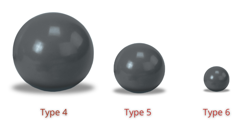
| Powder Type | Particle Size > 80% | Min Stencil Aperture (5-ball rule) | Surface Area Ratio | ||
| µm | Mil | µm | Mil | ||
| Type 1 | 75–150 | 6–3 | Not used in modern SMT | ||
| Type 2 | 45–75 | 3–1.8 | 380 | 15.0 | 1.5–2 |
| Type 3 | 25–45 | 1.8–1.0 | 230 | 9.0 | 1.2–1.5 |
| Type 4 | 20–38 | 1.5–0.8 | 190 | 7.5 | 1.0–1.2 |
| Type 5 | 15–25 | 1.0–0.6 | 130 | 5.0 | 1.5–2.0 |
| Type 6 | 5–15 | 0.6–0.2 | 76 | 3.0 | Varies |
| Type 7 | 2–11 | 0.4–0.08 | 56 | 2.2 | Varies |
| Type 8 | 2–8 | 0.3–0.08 | Varies | Varies | Varies |
.png)
The image showcases three common aperture shapes used in stencil printing: Circle, Square, and Squircle. These apertures are openings in the stencil through which solder paste is dispensed onto the printed circuit board (PCB). Circle: A classic and widely used shape, offering a clean and symmetrical solder deposit. Square: Often used for larger components or when a more rectangular pad shape is required. Squircle: A hybrid shape between a circle and a square, balancing circular and square characteristics.
All apertures in this image are 1:1 with the pad design, meaning their dimensions match the corresponding pad on the PCB. This ensures optimal solder paste placement and reduces the risk of defects like bridging or voids.
The 5-ball rule is a valuable tool for manufacturers as it provides a quick and easy way to estimate the appropriate solder paste particle size for a given PCB design. However, it's important to note that this is a general guideline, and there may be exceptions depending on specific factors such as component density, stencil thickness, and soldering process. While the 5-ball rule is a useful starting point, manufacturers should also consider conducting experiments and testing different particle sizes to determine the best fit for their specific application.
.png)
.png)
Aspect Ratio
Aspect Ratio = Aperture Width / Stencil Thickness
Defined as the ratio of stencil thickness to aperture width.
A minimum aspect ratio of ≥ 1.5 is generally recommended to ensure reliable paste release from the stencil aperture.
Area Ratio
Area Ratio = (Aperture Area) / (Aperture Perimeter × Stencil Thickness)
Defined as the ratio of aperture opening area to the stencil wall area.
A minimum area ratio of ≥ 0.66 is typically required to achieve consistent paste transfer and avoid deposition defects.
By Solder Paste Flux
Flux is used to remove oxides, prevent re-oxidation, and improve wetting to ensure reliable solder joint formation. The IPC J-STD-004C standard classifies fluxes based on composition (rosin, resin, organic), activity level (low, moderate, high), and halogen content. These parameters define the flux’s cleaning capability, wettability, and residue characteristics, forming a complete designator for selection and control.
Solder materials are broadly categorized as Clean (water-soluble) and No-Clean. Clean fluxes are more chemically active and require post-solder cleaning, while No-Clean fluxes leave minimal residue and typically do not require cleaning. However, in high-reliability or high-performance applications—such as high-speed electronics, underfill processes, or cosmetic-sensitive assemblies—even No-Clean residues may be removed.
Halide-containing fluxes are easier to clean but leave more residues, whereas halide-free No-Clean fluxes produce minimal residue but often require specialized cleaning solutions when removal is necessary.
| Flux Composition | Partial | Activity | Partial | With Halides | No Halides |
|---|---|---|---|---|---|
| Rosin | RO | Low | ROL | ROL1 | ROL0 |
| Moderate | ROM | ROM1 | ROM0 | ||
| High | ROH | ROH1 | ROH0 | ||
| Resin | RE | Low | REL | REL1 | REL0 |
| Moderate | REM | REM1 | REM0 | ||
| High | REH | REH1 | REH0 | ||
| Organic | OR | Low | ORL | ORL1 | ORL0 |
| Moderate | ORM | ORM1 | ORM0 | ||
| High | ORH | ORH1 | ORH0 | ||
| Inorganic | IN | Low | INL | INL1 | INL0 |
| Moderate | INM | INM1 | INM0 | ||
| High | INH | INH1 | INH0 |
Presentations
General Understanding on Fluxes
This presentation provides a comprehensive introduction to fluxes used in electronics soldering and PCB assembly. It explains the functions of flux, different flux chemistries, activation mechanisms, and residue classifications, while discussing their impact on solderability, joint reliability, cleaning requirements, and overall manufacturing performance.
By Solder Paste Material
Solder paste can be classified based on its material composition, primarily into lead-containing and lead-free types.
What is a Lead Solder?
Lead solder is a metallic alloy primarily composed of lead (Pb) and tin (Sn), often with small amounts of other elements like antimony (Sb) or copper (Cu). Historically, these alloys have been used to join metals by melting the solder and allowing it to solidify between the pieces. Compared to other metal alternatives, lead solder cools more slowly. This reduces the chance of the joint breaking and is effective in wetting joints. Lead solder has a lower and precise melting point, making it easier to control in automated PCB assembly and less likely to damage electronic components during the soldering process.
What is a Lead-Free Solder?
Lead-free solder is a metallic alloy used for joining metals that does not contain lead (Pb). It's made without harmful lead and uses metals like tin, copper, silver, bismuth, or antimony. These alloys are designed to replace traditional lead-based solders due to the environmental and health concerns associated with lead.
Compared to lead-based solders, lead-free solders typically have higher melting temperatures, requiring adjustments in soldering processes. Lead-free solders often exhibit different mechanical properties, such as higher strength and hardness, compared to lead-based solders.
Some common lead-free combinations include Tin-Silver-Copper (SnAgCu) alloy, Tin-Copper (SnCu) alloy and Tin-Bismuth (SnBi) alloy. Choosing the right lead-free solder depends on the specific needs of the electronic product. Factors like component compatibility, thermal cycling requirements, and joint reliability need to be carefully considered when selecting a lead-free solder.
What is the Reflow Profile of a Solder?
.png)
A reflow profile is a specific temperature sequence that a PCB with applied solder paste is subjected to in order to melt the solder and create electrical connections between components and the PCB. The standard reflow profile has four zones: preheat, soak, reflow and cooling. The profile in the picture above will serve as a typical reference [benchmarking SAC305 solder paste reflow profile] and describe the ideal temperature curve of the top layer of the PCB.
Reflow Profile Overview
A reflow profile defines the thermal process used to form reliable solder joints through controlled heating and cooling stages.