Thermal Gap pads
Pad & Dispensable form
-
Home

-
Products
-
Thermal Interface Materials
- Thermal Gap Pads
Thermal Gap Pads
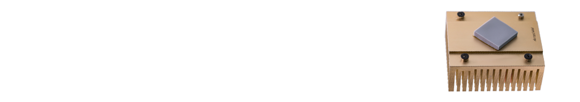
Thermal Gap Pads (TGPs) provide high thermal performance with ease of use for many applications. Ultra-high compressibility enables low stress and excellent conformity to mating surfaces. Honeywell Thermal gap pad models are naturally tacky, and require no additional adhesive which could inhibit thermal performance.
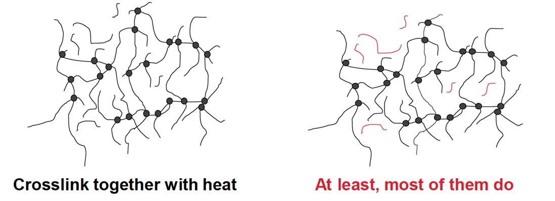
Thermal gap pads provide thermal performance with ease of use across a multitude of applications. They have been designed to minimize thermal resistance at interfaces, exhibit minimal bleeding and maintain effective performance through reliability testing. TGP models are silicone based, therefore they offer a certain anti-shock effect, with electrical isolation and non-flammability. While all interfaces bleed (with zero exceptions), our pads exhibit very low bleeding even under pressure due to the low molecular weight of the remaining unlinked chains.
A range of thicknesses from 0.5mm to 5.0mm are available. Honeywell TGP models come with two surface liners, which enable users to remove the liner after installation (before operation), with no contaminant risk and easier handling.
-


HGP12 | High Thermal Conductivity Gap Pad
- 0.13 Thermal Impedance
- 12 Thermal Conductivity
- Low oil bleeding & Low volatile
- 12 weeks
-

HGPA12 | High Thermal Conductivity Gap Pad
- 0.14 Thermal Impedance
- 12 Thermal Conductivity
- Low oil bleeding & Low volatile
- 10 weeks
-


DOWSIL™ TC-4525 CV Thermally Conductive Gap Filler
- Controlled silicone volatility (CV)
- 2.5 W/m-K Thermal Conductivity
- Applicable for Vertical Position
- 5 weeks
-

DOWSIL™ TC-5515 LT Low Density Thermal Conductive Gap Filler
- Low Density, Soft, & Compliant cured material
- Room-temperature cure in 360 minutes at 25°C
- Tacky surface after cure
- 5 weeks
-

DOWSIL™ TC-5533 Gap Filler
- Designed specifically for EV battery module
- Controlled siloxane volatility
- Vertical Stability
- 5 weeks
-

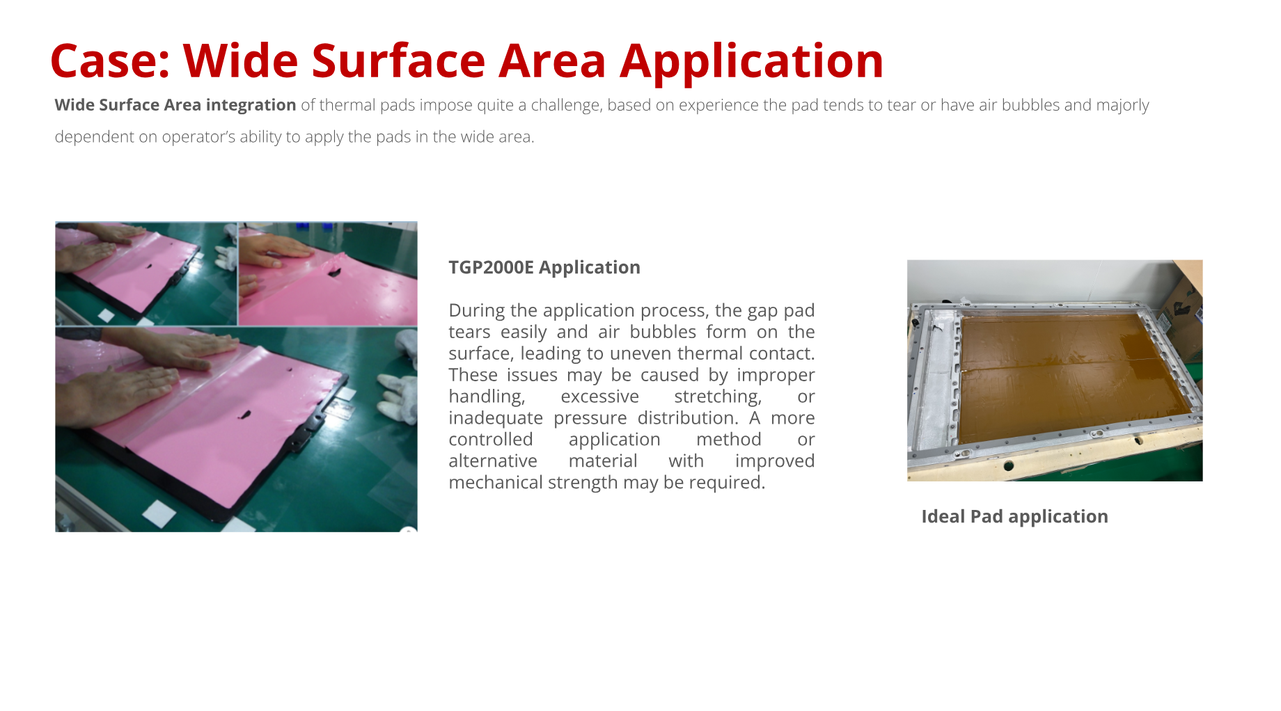
TGP 2000E | Thermal Gap Pad
- 0.95 Thermal Impedance
- 2.0 Thermal Conductivity
- Excellent surface wetting
- 8 weeks
-

HGP14 | High Thermal Conductivity Gap Pad
- 0.10 Thermal Impedance
- 14 Thermal Conductivity
- Low oil bleeding & Low volatile
- 12 weeks
Product Selector Guide
| Product name | Color | Thickness (mm) | Hardness (Shore00) | Specific Gravity | Thermal Conductivity (W/m·K) | Thermal Impedance(˚C·in2/W)(1mm@10psi)1 | Dielectric Strength (kV/mm) | Dielectric Constant @1MHz | Volume Resistivity (ohm·cm) | Flammability Rating |
|---|---|---|---|---|---|---|---|---|---|---|
| HGP14 | Grey | 0.5-2 | 60 | 3.3 | 14.0 | 0.1 | - | 8.3 | 1.0 x 10¹³ | V-0 |
| TGP1200 | Blue | 0.5-5 | 30 | 1.7 | 1.2 | 1.03 | 5 | 4.5 | 4.0 x 10¹² | V-0 |
| TGP1500 | Grey | 0.5-5 | 40 | 1.8 | 1.5 | 0.94 | 5 | 5.5 | 2.0 x 10¹³ | V-0 |
| TGP2000E | Red | 0.5-5 | 50 | 2.3 | 2.0 | 0.95 | - | 5.5 | 1.0 x 10¹⁴ | V-0 |
| TGP3000 | Yellow | 0.5-5 | 40 | 3.1 | 3.0 | 0.65 | 5 | 6.6 | 4.8 x 10¹³ | V-0 |
| TGP3000E | Green | 0.5-5 | 50 | 2.9 | 3.0 | 0.50 | >10 | 5.5 | 1.0 x 10¹⁴ | V-0 |
| TGP5000 | Blue | 0.5-5 | 45 | 3.3 | 5.0 | 0.3 | 5 | 5.0 | 8.0 x 10¹³ | V-0 |
| TGP6000 | Grey | 0.5-5 | 40 | 3.3 | 6.0 | 0.25 | 5 | 8.5 | 3.79 x 10¹⁵ | V-0 |
| TGP7500C | Brick Red | 0.5-5 | 20 | 3.5 | 7.5 | 0.16 | 7 | 8.1 | 1.0x10¹⁵ | V-0 |
| TGP8000 | Grey | 0.5-5 | 30 | 3.4 | 8.0 | 0.2 | 5 | 8.3 | 6.47 x 10¹⁵ | V-0 |
| TGP8000HV | Grey | 0.5-5 | 60 | 3.5 | 8.0 | 0.2 | 8 | 8.3 | 6.47 x 10¹⁵ | V-0 |
All values mentioned above are typical values and not product specifications. The technical data contained herein are intended as reference only. Please contact Honeywell or Caplinq for assistance and recommendations on specifications for this product.
Frequently Asked Questions
What is the standard size and tolerance of Thermal gap pads?
TGP model thermal gap pads are available in standard sheets and also custom die-cut parts, and in a range of thicknesses. It is very important to understand that the applied pressure will directly affect the bondline thickness and the thermal impedance values
Thickness Range: 0.5-5.0mm with 0.25mm incremental
Thickness Tolerance: >1mm, ±10% 0.5-1mm, ±0.1mm
What is the dielectric strength of Thermal Gap Pads?
Unless it is otherwise listed, the dielectric strength of the gap pads is around 5 - 7 kV/mm while High voltage versions have a dielectric strength around 7.6 - 7.9 kV/mm. Since air voids can occur it is hard to guarantee the exact Breakdown Voltage but you can take 5000V as the base value for non HV version pads. We are actively researching higher Dielectric Strength product versions. Contact us for developmental pads that can reach up to 9.6 kV/mm.
What happens after the expiration date?
Product shelf life is guaranteed when it is stored in the suggested conditions under controlled humidity. After the product "expires" the most readily observed response is precut pads (kiss-cut) tend to stick to each other and there is difficulty peeling out one without damaging adjacent one. There will be some viscosity change that may or may not affect thermal performance and we will not test or recertify material. We will not be liable for product quality or performance issues if expired parts are used in manufacturing.
What is the risk involved in using PCM Materials after the shelf life?
The material could potentially still be used after the shelf life. The risk involve in using materials after their shelf life is the inherent moisture absorption of all polymers, including these PCM materials as well. Moisture related failures are a big concern, and could severely impact the TIM performance. However, an expert in TIMs shared that if the material is baked (>100 °C) for a certain period of time (~30 min), the build up moisture could be evaporated quite easily and used afterwards. We will not be liable for product quality or performance issues if expired parts are used in manufacturing.
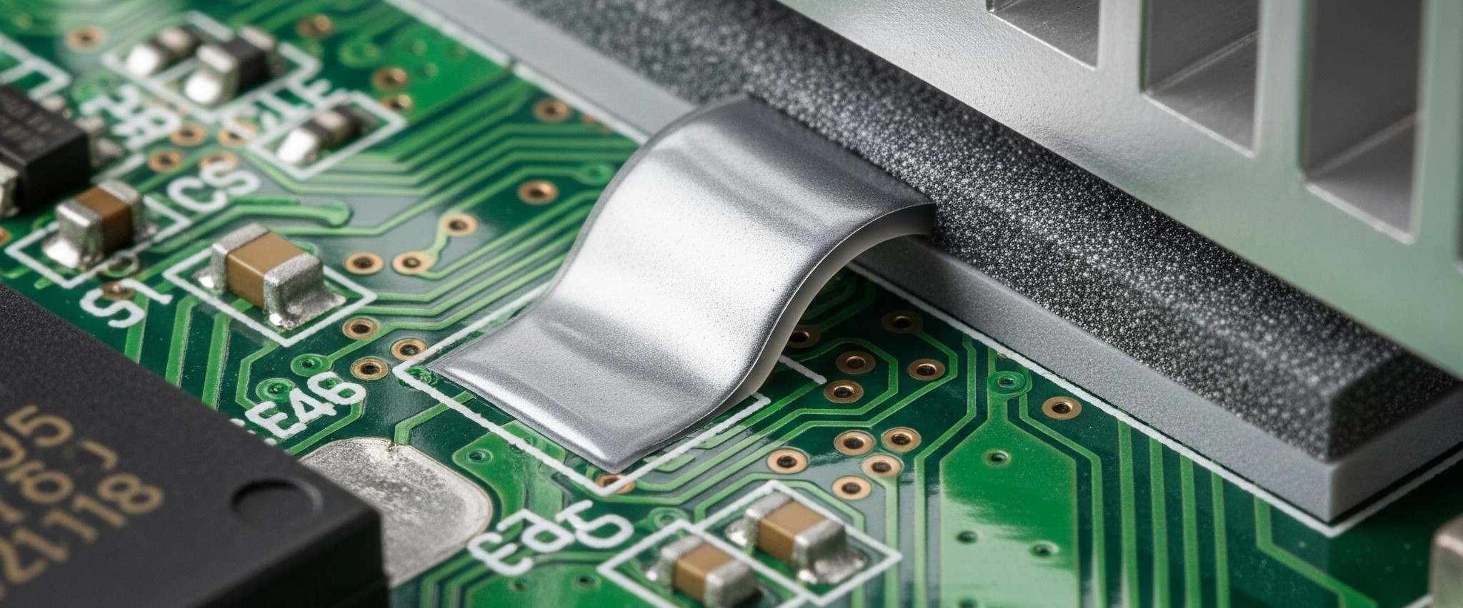
What is a Gap Filler?
Gap filler is a Thermal interface material that exists between heat dissipating and heat generating surfaces and takes up the tolerance variation.It is silicon based, filled with TC fillers such as Bn,Zn and Alumina and comes in sheet (gap pad) or dispensable (putty) form.
What is the operating temperature of Thermal Gap Pads?
Thermal Gap Pads are normally used in operating temperatures up to 80°C - this being the maximum temperature of the surrounding area. However, because of chemistry of these pads, they can easily withstand temperatures from -60 up to 200°C
Can a 2mm thick Gap Pad be supplied in a Tape and Reel Format?
We cannot provide reel format for 2mm thermal gap pad. Different process was tried for the rolling packaging but wrinkles always occurs for 2mm thickness and it cannot get recovered.
Does the TGP Series release any volatiles or outgassing during use?
The TGP Series is silicone-based, and therefore a small amount of outgassing is expected due to the inherent properties of silicone materials. However, the total amount of volatile release is very minimal typically less than 0.5% to 1%. For certain low-volatile (LV) grades, the outgassing is further minimized and strictly controlled within 0.1% to 0.2%.
Learn More
Thermal Gap Pads
A gap filler material is a type of thermal interface material to fill the gap (>0.5mm), while phase change material and thermal grease are designed for thin bondline thickness (<0.1mm) applications. It is expected to be compliant enough to deflect to accommodate multiple module heights and tolerance variation within applications without generating excessive levels of pressure within the system. Thermal gap pads, thermal putty pads, two-part hybrid gels, and one-part hybrid gels are all considered as gap filler materials.
Key Features Of Gap Filler
)(4).png)
Thermal Gap Pad Selection Guide
Thermal conductivities, boneline thickness and reliability capabilities are the most important considerations for TIM selection. This also works for thermal fillers like thermal gap pads. However, there are some other features need to be considered specifically for gap filler pads:
).png)
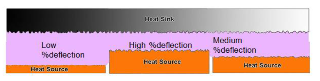
Compression
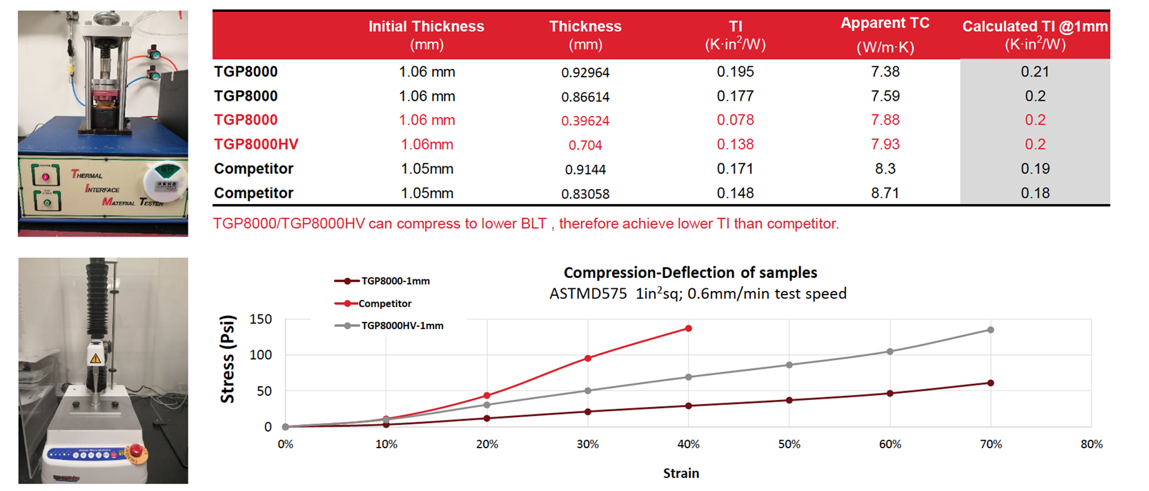
Some compression (at least 10% compression) is required to overcome/decrease the contact thermal resistance. The relationship between deflection and compression is not linear. You could find the Stree-Strain Curve of compression properties on each product page. For example, the figure below shows the TGP8000 and high breakdown volatge version TGP8000HV's compressibility and how TI (thermal impedance) & Thickness change by compression ratio.
Difference between Peak Stress and Residual Stress
In gap compression applications, particularly involving thermal interface materials (TIMs), peak stress and residual stress represent different stages of mechanical behavior during and after compression. Peak stress refers to the maximum stress exerted on the material during the compression process. It occurs at the moment when the TIM is being compressed to bridge the gap between surfaces, and it reflects the material's initial resistance to deformation. A higher peak stress typically indicates a stiffer or thicker material, which may require greater force during assembly.
In contrast, residual stress is the remaining stress in the material after the compressive force has been released. It reflects the material's ability to retain pressure and maintain contact over time, which is critical for long-term thermal performance and mechanical stability. Residual stress provides insight into the elastic recovery or permanent set of the TIM, influencing how well it continues to conform to surface irregularities and maintain thermal conductivity throughout its service life.
Thickness Tolerance
When starting the design process, identify the nominal gap and know the tolerances. The thickness range of thermal gap pads we provide is 0.5-5.0mm with 0.25mm incremental. Thickness Tolerance: ±10% while thickness>1mm; ±0.1mm while thickness is 0.5-1mm
Hardness
Ideally, the softer the gap filler material, the better, since high assembly pressure may cause gap bleeding out and components deformation. However, materials that have a higher thermal conductivity and more curing extent, the harder it gets due to the high filler content. It is harder for high TC product to own elasticity and bounce back while pressure is moved away.
Additional Layer
Some reinforcement carriers might be added on normal gap pads to enhance specific properties as customers need. Some common ones are:
- Woven Fiberglass (no PSA) to provide reinforcement against tearing down and a clean low tack interface surface
- Polyimide Film Or PEM Film to offer an excellent dielectric strength and permit gap pad to see a shearing motion
- Aluminum Foil (with PSA) to allow a pressure sensitive adhesive on the gap pad
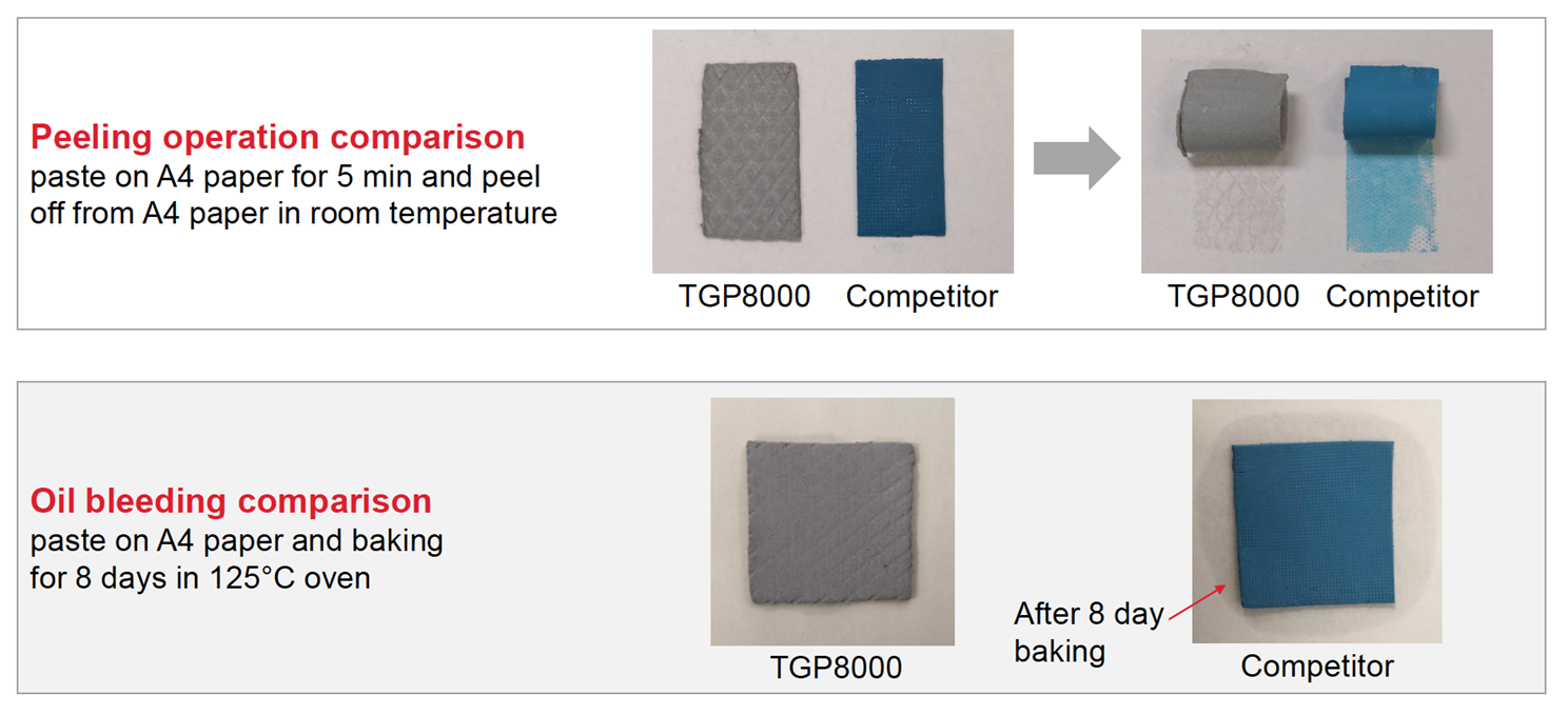
Minimize Thermal Pad Bleeding
Enhance Thermal Gap Pad Breakdown Voltage
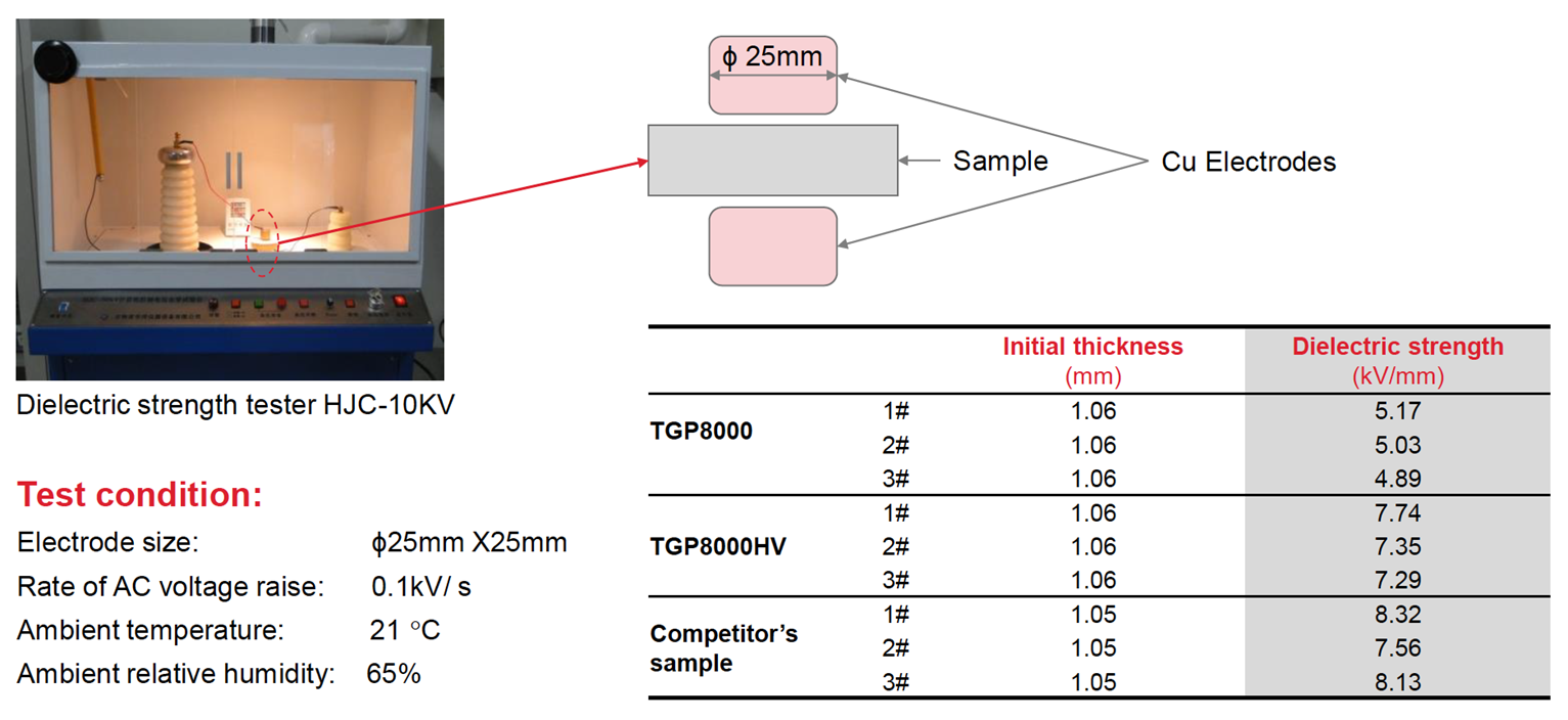
While bleeding tests are not standardized, Dielectric strength testing is quite straightforward. The sample is placed between two 25 x 25mm Copper electrodes in ambient temperature and 65% ambient relative humidity while the voltage is raised by 0.1kV/s until the AC current crosses through. Optically, this cross through is usually in a form of a pinch/hole in the material, sometimes invisible to the bare eye. Tests are being conducted in a Dielectric strength tester - HJC-10KV at the time of writing of this content.
Honeywell's TGP8000HV has the lowest Thermal impedance out of all the entire thermal gap pad portfolio, plus higher breakdown voltage than the plain TGP8000 version. Check the dielectric strength data of TGP8000HV below.
Thermal Gap Pads vs. Thermal Putty Pads
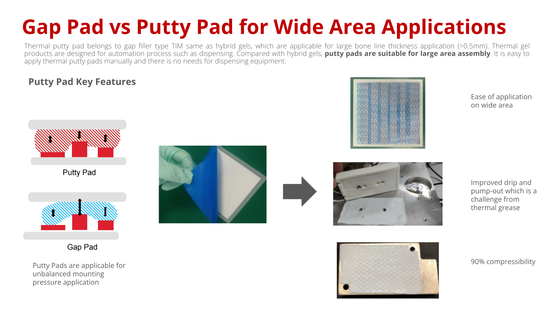
Compatibility of Putty Pads and Gap Pads with Immersion Cooling Fluids
Immersion cooling has been gaining significant attention as a thermal management strategy, especially for high-performance electronics and data centers. A common question we receive is whether thermal interface materials (TIMs), particularly putty pads and gap pads, are compatible with dielectric immersion fluids such as polyalphaolefin (PAO)-based fluids.
Putty Pads and PAO Compatibility
From our experience and testing, putty pads are not recommended for use in PAO-based immersion cooling systems. PAO fluids belong to the class of carbon-based dielectric liquids. Both silicone-based and silicone-free gap fillers tend to swell in PAO fluids, with the extent of swelling depending largely on the material’s crosslink density.
Putty pads are typically formulated with a lower degree of crosslinking, which makes them especially vulnerable. In fact, when fully immersed in PAO fluids, putty pads can fail in as little as two days of continuous exposure. While survival times are longer when the material is compressed between a heatsink and electronic components (since the pad is not fully exposed to the fluid), their use is still not recommended for immersion cooling applications due to long-term reliability risks.
Thermal Gap Pad as an Alternative
In immersion cooling systems, low-thermal-conductivity (1–2 W/m·K) gap pads are often not an option, as fluid circulation itself provides effective heat removal. Instead, higher thermal conductivity gap pads in the 3–5 W/m·K range are widely adopted, especially in markets such as China.
For these applications, our TGP3000 to TGP5000 series gap pads are a better choice. These materials are engineered with a higher crosslink ratio in their formulation, which improves their stability and compatibility in immersion environments compared to putty pads.
For critical components such as main processors or high-power chips, customized solutions like Indium metal pads can also be considered, offering excellent performance in direct liquid-contact cooling scenarios


