
Power Conversion Systems
Chargers, Converters, Inventers
- Home

- eMobility
- Power Conversion Systems
- Inverters
Inverters
Basic Fundamentals of Inverter
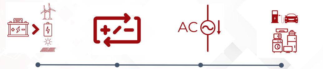
The power inverter takes DC power as its input. This DC power source is typically a battery, although inverters can also be connected to solar panels, wind turbines, or other DC power supplies.
Power inverter is the DC-to-AC converter. This stage involves using electronic components, usually transistors or MOSFETs, to rapidly switch the DC input on and off. This switching creates an oscillating current that approximates the sine wave of standard AC power.
The oscillating current generated in the converter stage is then passed through an output filter to smooth out the waveform and reduce harmonic distortion.
AC output that can be used to power household appliances and electronic devices
Power Inverters for Electric Vehicles
Technological advancements in the electric vehicle power inverter sector have played a crucial role in the growth of the market. Several technological advancements in electric vehicle power inverters have been made in recent years.
Power inverters used in electric vehicles are now capable of handling higher voltage and power ratings than ever before. This allows electric vehicles to travel longer distances on a single charge and to have faster acceleration and top speeds. Table 1 below show the summary of the rated power and power densities of the reviewed traction inverter implementations:
Inverter Power Density and Specific Power in recent EVs | ||||
|---|---|---|---|---|
Model | Components | Total Power Rating * (kVA) | Power Density (kVA/L) | Specific Power (kVA/kg) |
Chevy Volt PHEV (2014) | Dual inverter | 180 | 17.3 | 21.7 |
Cadillac CT6 PHEV (2016) | Dual inverter | 215 | 22.6 | 16.0 |
Toyota Prius HEV (2016) | Applicable to various feeds Dual inverter, boost converter and APM | 162 | 23.7 | 13.6 |
Nissan LEAF BEV (2012) | Single inverter | 80a | 7.1 | 4.7 |
BMW i3 BEV (2016) | Single inverter, charger and APM | 125a | - | 6.6 |
Audi A3 e-Tron PHEV (2016) | Single inverter and APM | 75a | 9.4 | 7.4 |
Tesla Model S 70D BEV (2015) | Single inverter | 193a,b | 30.1 | 33.3 |
* Total power rating is typically reported for only the inverter(s) while the mass and volume is reported for all components contained in the inverter housing,resulting in lower than actual estimates of power density and specific power. All values are peak output powers. a Values are reported motor power in kW. Inverter kVA rating is likely slightly higher, resulting in lower than actual estimates of power density and specificpower. b Motor power as previously reported by Tesla | ||||
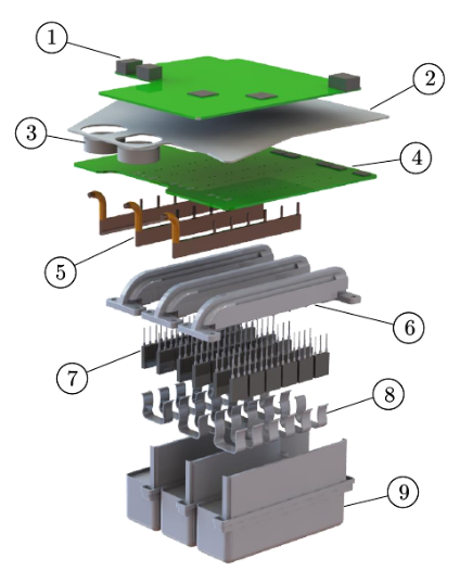
Current EV Market Designs
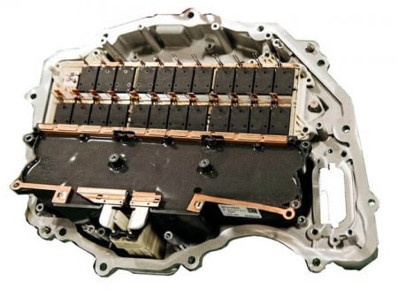
![Fig. 4. Nissan LEAF inverter components [53]: 1) Control board. 2) DC-link capacitor. 3) DC-link busbar. 4) Phase busbars. 5) Current sensor. 6) Gate driver board. 7) IGBT power modules. 8) Serpentine heat sink.](https://lh7-us.googleusercontent.com/H3x_6xB1kcnvfFLnFEZ1183LdZ6dMNpcfEYLH37Ol2OD4umkTheYX3FUc8L00fka5mu-NZ5T8UWA2Inxsc49fv_jlfVMKK7vWSGCYNwx5Vt5xY_aOBmD-5Kc7PZxcS_u94wqPbps7RwNjWBLPNlNRcqG9w=s2048)
Toyota “power card” DSC IGBT module stack with heat exchanger
Silicon Carbide, Gallium nitride and other exotic die arrangements have (on paper) revolutionized the inverters, allowing for higher switching speeds with lower system weight. These switching speeds - even though benefiting the power conversion - can cause EMI interference and wave reflection and dent the insulation. There are theoretical solutions to this issue that are slow to materialize because of the SiC adoption rate into large-scale high power applications.
BorgWarner Viper Inverter Model
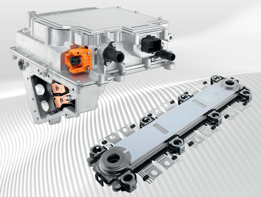
Borgwarner High Voltage Inverters
Technical Features:
- Using the Viper power switch patent. The switch has the dual-sided cooling capabilities. This unique cooling structure provides a more compact, efficient power module. When compared with previous generations of inverters, this dual-cooled power switch enables weight reductions of 40%, overall size reductions of 30% and higher power densities of 25%.
- The switch’s design also eliminates wire bonds – the complex web of wiring that provides the path for the current to flow through the switch via the inverter’s connections to and from the battery and motor. Eliminating the wire bonds and moving to soldered interconnectors, translates into better durability.
- The use of silicon carbide (SiC) MOSFET. SiC devices offer 2–3 times lower on-state voltage drop than Si, 10x higher breakdown field than Si. It has better thermal conductivity and better high-temperature stability. The higher voltage means that the cables are lighter than the low-voltage cables. It also has a smaller power size than silicon and a faster switching speed. Faster switching speeds mean lower switching losses, with SiC reducing switching losses by 70%. Therefore, it is especially suitable for high switching speed or power occasions. The advantages of SiC power electronics are particularly evident in 800 V battery systems.
Power Inverter: Power Module Thermal Design
Power modules are the major, key elements of the power conversion emobility systems. Being able to reduce the size of existing arrangements or packing double the power in current inverter sizes is a global trend that drives the e-mobility crowd. These fast switching systems need to have controlled waveforms with high frequency responses that allow for minimal losses and as a result, better performance and reliability.
Power modules consist of:
IGBT (integrated gate bipolar transistor) modules
MOSFET (metal oxide semiconductor field effect transistor) modules
IPMs (intelligent power modules)
SIP (system in package) modules.
Power modules are used extensively in high power inverter applications like alternative energy conversion, battery backup systems, motor drives for industrial equipment, electric vehicles, traction and shipping.
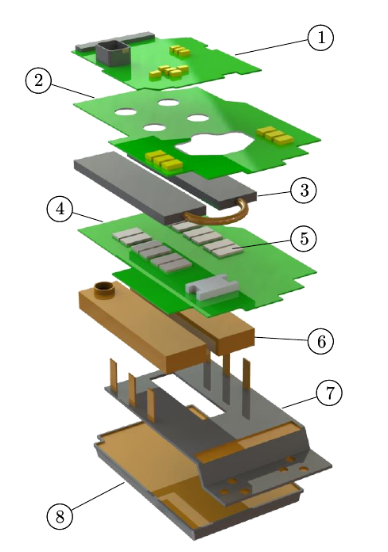
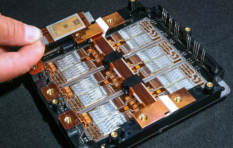
Tesla Model 3 Main Inverter
Application Trends
- Smaller size and lower weight
- Higher Frequency and high power rating
- Built-in. Integration capability
Finally, integration cannot be achieved without getting rid of cables and useless interconnections. This is only possible with busbars, requiring busbar coating powders with great electrical insulation to be able to make compact and integrated designs.
Power Module: Subcomponents
Power modules can be anything from IGBT modules to MOSFET , IPMs and SIP modules. They are used extensively in high power inverter applications. These modules are mainly lead by next gen dies such as Silicon Carbide, Gallium Arsenide and Gallium nitride, with the later being reserved mainly for smaller, consumer-grade applications. Gate driver controllers can use all of those technologies depending on the output and performance requirements.
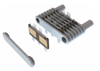
SiC Switches in Viper Inverter (Borgwarner)
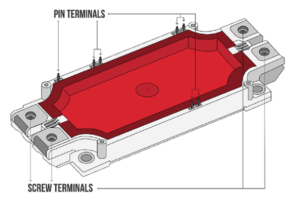
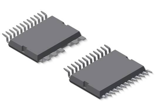
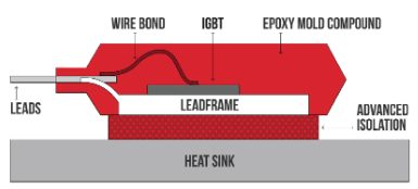
IGBT Package
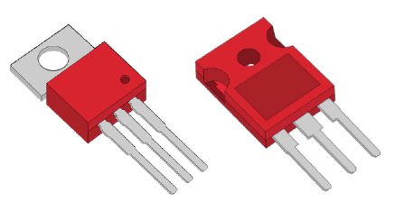
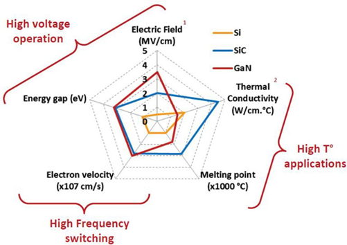 Chart. Power Module Component properties for different applications
Silicone Carbide Switches. These MOSFET devices help us pack more punch in a smaller space and allow devices such as power control units to operate. Their vertical design and the very high performance of SiC makes it a major step ahead of the IGBT power modules. The problem with all this power is that it generates heat that needs to be dissipated very efficiently in order for the device to continue to operate. This bring material challenges that can only be solved with cutting edge thermal interface materials and epoxy molding compounds.
Gallium Nitride Switches. These GaN switches have ridiculous switching speeds, up to 2MHz but are limited to specific types of applications for the time being. They are mainly stacked vertically but their exotic high electron structure makes them cost ineffective for large-scale applications (for now). They work amazingly well with chargers and other such devices and are the main reason your latest 120W brick can charge your phone in 15 minutes.
DC link capacitors
DC link capacitors can be either film or electrolytic capacitors that are used as plugins by being mounted directly on IGBTs. They have self healing capabilities, coming from their metallized dielectric propylene and can maintain an exquisite dielectric in harsh operating conditions and elevated temperatures. They need to be able to withstand temperatures up to 125°C for long operating periods of time.
Their self healing function ensures high reliability, high capacitance stability and a very limited capacitance loss throughout the product's life span. Among others, they can be used for DC/AC inverters for wind and solar applications and are commonly found in frequency inverters. These intermediaries reduce the power transfer noise during the AC source conversions and are crucial for the high power circuits that they are commonly used.
SiC TO packages
Silicone Carbide TO packages are a crucial part of the inverter. Read all about them in our Transistor outline application pageThermal Management Solution for Inverters
Inverter components require thermal interface materials that can keep up with the market trends and the ever-changing requirements. These components are critical for the thermal design of power modules and can be a literal life or death decision that has to be taken. As you can see, thermal management is crucial since more power always warrants more heat and hence more thermal dissipation needs. That's why we have a range of Thermal interface materials, made for power modules such as PTM-6000HV
Thermal Interface material Application considerations:
- Excellent Thermal Performance
- Low thermal resistance down to 0.04 ˚C·cm2/W
- High thermal conductivity (up to 8 W/mK)
- Optimal Surface Wetting & Low Contact resistance
- Great conformability to fill up microscopic voids and cavities
- High Reliability and Long-life
- No bleed-out, pump-out and flow out issues
- No aging effects including dry-out over time and degraded thermal performance
- Stable thermal impedance across accelerated aging test
- Manufacturability
- Easy assembly & broad process window
- High yield with low/zero material waste
- Pad and paste form factor
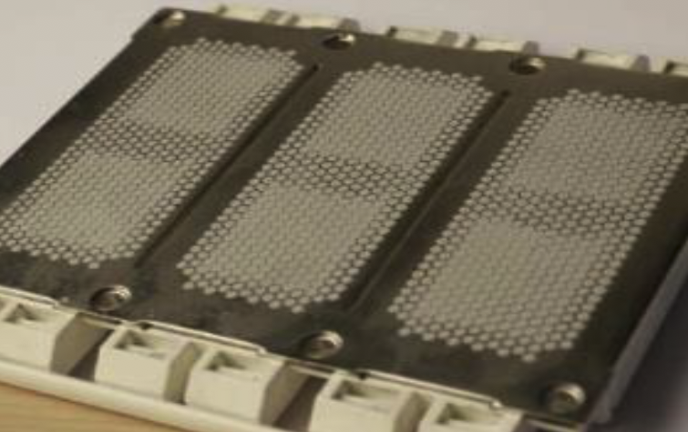
Figure: Phase Change Material applied in IGBT as honeycomb structure.
Phase change materials (PCM) are designed to minimize thermal resistance at interfaces and maintain stable performance through the rigorous reliability testing required for long product life applications.
Their main benefits are:
- Min BLT 20~30um
- High thermal conductive
- Non silicone based material
- No pump out, bleed out, dry out issue
- Superior long-term reliability
- Stencil printable and dispensable
Product | Thermal Impedance (℃-cm2/W) | Thermal Conductivity (W/m-℃) | Reliability | Pad Thickness (mm) | Remark |
0.04 - 0.06 | 6.0 - 8.0 | >1500 | 0.20 - 1.00 | High Thermal Performance | |
0.06 - 0.08 | 3.5 - 4.5 | >3000 | 0.20 - 1.00 | Advanced Reliability | |
0.10 - 0.12 | 2.5 - 4.0 | >3000 | NA | For IGBT Application | |
0.06 - 0.08 | 3.5 - 4.5 | >1000 | 0.20 - 1.00 | ||
0.09 - 0.12 | 2.0 - 2.5 | >600 | 0.20 - 1.00 | ||
0.12 - 0.14 | 1.8 - 2.4 | >600 | NA | Paste Only |
Thermal Gap Pads (TGPs) provide high thermal performance with ease of use for many applications. Ultra-high compressibility enables low stress and excellent conformity to mating surfaces. Honeywell Thermal gap pad models are naturally tacky, and require no additional adhesive which could inhibit thermal performance.
Thermal gap pads provide thermal performance with ease of use across a multitude of applications. They have been designed to minimize thermal resistance at interfaces, exhibit minimal bleeding and maintain effective performance through reliability testing. TGP models are silicone based, therefore they offer a certain anti-shock effect, with electrical isolation and non-flammability. While all interfaces bleed (with zero exemptions), our pads exhibit very low bleeding even under pressure due to the low molecular weight of the remaining unlinked chains.
Product | Thermal Impedance (℃-cm2/W) | Thermal Conductivity (W/m-℃) | Volume Resistivity (Ω-cm) | Hardness Durometer | Remark |
0.95 | 2.0 | 1014 | 50 | Excellent Surface Wetting | |
0.65 | 3.0 | 4.8 x 10¹³ | 40 | Low pressure vs Deflection | |
0.30 | 5.0 | 8.0 x 10¹³ | 45 | Good elastic modulus | |
0.25 | 6.0 | 3.8 x 10¹⁵ | 40 | Excellent Surface Wetting | |
0.20 | 8.0 | 6.5 x 10¹⁵ | 30 | Low oil bleeding | Outgassing | |
0.20 | 8.0 | 6.5 x 10¹⁵ | 60 | High Breakdown Voltage |
Encapsulation (EMC) for Inverters
Key Considerations
- Excellent Thermal Stability Pass thermal cycling test
High Tg as required
Low weight loss by TGA test and low thermal expansion
- Excellent Electrical Stability Pass HTRB test
Low ion content and low ionic mobility at high power condition
Stable ionic conductivity and permittivity at high temperature condition;
- Reliability for SiC MOSFETs Packages Pass MSL test
Low moisture absorption
Low storage modulus
Superior adhesion to lead frame
Low Coefficient of Thermal Expansion (CTE) - Environmentally Friendly
Green material without Br/Sb comply with RoHS;
Suitable for halogen-free devices defined by the Jedec JS709B;
Hysol GR15F-MOD2C
The material has high Tg (235C) which is qualified and in use in 2nd generation SiC MOSFET of world's leading manufacturer of SiC based diodes for Power control and management.
Hysol GR15F-MOD2C is well suited for SiC devices. Older generation silicon Si MOSFETS operated at (only) 600V. New Silicon Carbide devices operate at 1200V. These new 1200V MOSFETS deliver power density and switching efficiency at half the cost per amp of our previous generation MOSFETs. CREE claims that with this new MOSFET platform, that they already have design wins in multiple segments like solar inverters and uninterruptible power supply (UPS) systems. They continue to say that due to rapid acceptance of this 2nd generation of SiC MOSFETs, CREE is shipping pre-production volumes ahead of schedule and ramping volume production in-line with customer demand.