
Water Electrolyzers
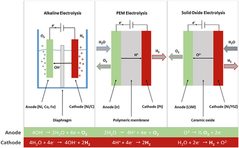
Alkaline, PEM and AEM Electrolyzers
- Home

- Renewable Energy
- Water Electrolyzers
- PEM Electrolyzers
PEM Electrolyzers
Electrolyzers and Fuel cells are opposite sides of the same coin. Fuel cells take hydrogen in and put electricity out, while electrolyzers take electricity in and produce hydrogen. Both of them have a similar membrane assembly and require a gas diffusion layer, but the gas diffusion layers used for them have different requirements.
The market is definitely calling for electrolyzers. Biogas plants for example, use the electrolyzers that generate the H2 to convert Carbon Dioxide into Methane and water. They are also used for Hydrogen fuel, for electromobility applications and power grid stabilization. Finally, remote hydrogen production, not necessarily for energy storage, but for the production of hydrogen is really driving the use of electrolyzers.
Proton Exchange Membrane (PEM) Electrolyzers
PEM electrolyzers use a Proton Exchange Membrane which use a solid polymer electrolyte.
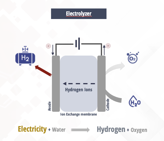
When current is applied on the cell stack, the water splits in hydrogen and oxygen and the hydrogen protons pass through the membrane to form H2 gas on the cathode side.
The polymer electrolyte membrane (PEM)-based electrolyzer is very popular, and many modern electrolyzers are built with PEM technology. The PEM electrolyzer uses the same type of electrolyte as a PEM fuel cell. Check Fuel Cell Page The electrolyte is a thin, solid ion-conducting membrane, which is used instead of the aqueous solution. Hydrogen produced by this type of electrolyzer is highly pure. (Link)
What is the operating principle of a PEM electrolyzer?
A PEM (Proton Exchange Membrane) electrolyzer is a device that uses an acidic polymer membrane as an electrolyte to split water molecules into hydrogen and oxygen through a process called electrolysis. The chemical principle behind a PEM electrolyzer is based on the principles of electrochemistry.
In electrochemistry, chemical reactions are driven by the transfer of electrons from one substance to another. When an electrical current is applied to an electrolyte solution, it causes the electrolyte solution to undergo a process called electrolysis. During this process, the electrical current causes the water molecules to be split into their constituent atoms of hydrogen and oxygen.
In a PEM electrolyzer, the process is made possible by the presence of the acidic polymer membrane, which acts as a proton exchange medium. The membrane is sandwiched between two electrodes, an anode and a cathode, which are both coated with catalysts to facilitate the reaction.
- When an electrical current is applied, water molecules at the anode are oxidized to form oxygen gas, positively charged hydrogen ions (H+), and electrons: 2H2O → O2 + 4H+ + 4e-
- The hydrogen ions are attracted to the cathode, where they pass through the polymer membrane, while the electrons flow through an external circuit to the cathode. At the cathode, the hydrogen ions combine with electrons and are reduced to form hydrogen gas: 4H+ + 4e- → 2H2
- Overall, the reaction can be expressed as: 2H2O → 2H2 + O2
The acidic polymer membrane plays a crucial role in the process by allowing the positively charged hydrogen ions to pass through it while preventing the negatively charged oxygen ions from passing through. This selective permeability is what separates the two half-cells and creates the necessary potential difference for the reaction to occur.
The catalysts on the electrodes also play an important role in the process by increasing the rate of the reaction. Typically, platinum groum metals are used as the catalyst on the electrodes in a PEM electrolyzer.
In summary, a PEM electrolyzer works by using an acidic polymer membrane as an electrolyte to facilitate the transfer of protons (H+) between the electrodes and the water molecules, resulting in the production of hydrogen and oxygen gas.
There have been interesting attempts to use an electrolyzer to combine with Nitrogen. That combination creates ammonia and that is what is actually used to generate electricity. By using ammonia as an energy source, there's no carbon dioxide that's burned off in the process.
LINQCELL has a number of different products and a number of different grades that are used for various applications. Thinner grades are typically used for fuel cells, medium ones are used for Vanadium redox batteries and finally thicker carbon panels are typically used for PEM electrolyzers.
In the PEM electrolyzers we are mostly referring to the Cathode stack where the GDL is used as a current collector. On the anode side, titanium-based current collectors are used.
As opposed to carbon paper, felt or cloth, the process of making the carbon panels allows them to be produced in very thick sheets. At the same time we are able to get very dense materials as well. So, the uniqueness of the carbon panels is the ability both a thick sheet and a very dense sheet. One of the thicker grades that we have right now is LINQCELL GDL 2900, a 2.9mm carbon panels/plate.
Carbon Plates VS Sintered titanium for PEM electrolyzers
Carbon papers can be used as Gas Diffusion Layers (GDLs) in PEM electrolyzers. GDLs are essential components of PEM electrolyzers that facilitate the transport of reactants (hydrogen and oxygen gas) to and from the electrodes, while also providing structural support and electron conduction.
Carbon paper is a popular material for GDLs in PEM electrolyzers because of its high porosity, good electrical conductivity, and chemical stability under the harsh operating conditions of the electrolyzer. The carbon fibers in the paper create a network of interconnected channels that allow the gas to flow through the electrode, while also providing a large surface area for the electrochemical reaction to occur.
However, it is important to note that the selection of the appropriate GDL material for a specific application depends on several factors, including the operating conditions (such as temperature, pressure, and humidity), the desired performance metrics (such as efficiency and durability), and the overall system design. Therefore, a thorough evaluation of the performance characteristics of different GDL materials should be conducted before selecting the appropriate GDL for a specific PEM electrolyzer application.
Compared to sintered titanium there's a thickness advantage for the carbon sheets. Sintered titanium can also be made thicker, but there's a liner relationshipt to the cost of the material. Carbon plates though do now have a linear cost relation when you go to thicker substrates. On the cathode side, there's also the long term reliability concern where compressed hydrogen makes sintered titanium malleable. Carbon panels do not exhibit the same effect.
These sheets can also be compressed quite significantly. 20% compressibility is not uncommon, depending on the grade, something that also creates a nice seal that aids with avoiding leakage. Sintered titanium on the other hand is not compressible at all. Pore size on Sintered titanium can be around 20-100um with a 30-50% porosity whereas carbon panels have a random pore distribution with an average pore size of 20um and a porosity of 70-75%. To add to that, Microporous layers can be applied directly on the carbon panel while in the case of sintered titanium a standalong MPL layer is required. Finally, the cost of carbon papers is significantly lower than the one of Sintered titanium, which can be twice as expensive in lower volumes.
Comparison of porous Current Collector materials | ||
Material Properties | LINQCELL Carbon Plate | Sintered Titanium |
|---|---|---|
Thickness | Thickness range from 125micron to 3mm. Cost has non-linear relationship. | Any thickness is possible, but cost has a linear relationship to thickness |
Oxidation on Cathode (H2) side | No such effect with the LINQCELL GDL | Presents longer-term reliability as the compressed H2 makes the sintered titanium malleable |
Compressibility | Can be compressed significantly. A 3mm thick sheet can compress to 2mm under pressures of 6-8MPa | Not compressible (rigid) at electrolyzer pressures |
Compression Set | No compression set. Near perfect hysteris after pressure is removed. | N/A – Not compressible |
Pore Size | Random distribution, average pore size is 20 micron | 20 – 100 microns |
Porosity | 70 – 75% | 30 – 50% |
Resistance Values | Slightly lower resistance values than with sintered titanium. Higher heat treatment decreases resistance. | Slightly higher resistance values obtained than with carbon panels |
Cost | Considerable price advantage of the carbon paper | Considerably more expensive. Twice as expensive in low volumes. |
Microporous Layer | Can be manufactured directly on the carbon paper | Requires a standalone MPL |
Under Pressure | Carbon paper tends to become brittle under higher pressure | No increased brittleness under pressure |
Electrical Conductivity | Requires at least 100 S/cm, the higher the better | |

How can you reduce the cost of PEM electrolyzers?
- The first thing you can do is increase the active area. A large active area decreases the cost per kg of H2 produced. Linqcell carbon panels are typically 40 x 40cm but larger sheets can be produced if there is a significant business case.
- High-pressure PEMS. If the GDLs are compressible than we eliminate a compression step that allows customers to buy less expensive compressors and reduce their overall costs. Linqcell papers withstand a significant amount of pressure and can be compressed up to 15-20% of their initial thickness, depending on the grade.
- Using Carbon panels instead of Sintered titanium reduces the material cost.
- Carbon panels have a very long useful life, usually outcompeting the ion exchange membranes themselves. so this is an extra cost saving step that graphitized carbon panels can help us with.
When we are looking specifically on how we can reduce the cost of the panels themselves, there are three areas that we're focusing on.
One area is to optimize the furnace runs. Furnace runs up to 2000°C are very expensive. With the rising cost of energy this is one the most important aspects of carbon panel production since this is almost one third of the cost. If we can optimize those and make sure that ovens are always full and we are taking full advantage of the space and consumed energy, we will be able to reduce the cost of the panels. This means that low volume run are very expensive since we are consuming the same energy either with 1 sheet or with 10000 sheets. Optimization is key. That's why there is a linear relationship between cost and the number of units produced.
Another one is machining costs. If we can work together to be able to accept a greater tolerance, then the machining cost which represents almost a third of the final cost can be reduced.
Finally, it comes down to materials and size. If you are asking for die-cut circles there is going to be a long of materials waste and machining cost. Custom molds can be made but the volumes and commitment needs to be there, in order to justify such an investment.
Applications of Carbon Panels
GDLs can be used in a variety of Technical Engineering Applications such as
- PEM Electrolyzers
- Fuel Cells
- Heat Management
- Redox Flow Batteries
- Gas Diffusion Layers
- Gas Diffusion Media
- Porous Graphitized Carbon Sheets
- Fuel Cell Powered City Buses
Benefits:
- Lower Cost compared to Titanium Mesh / Sintered Ti for Cathode (H2 Side) Electrode Thicker Plates (Up to 5mm)
- Higher Density (up to 1 g/cc)
- Higher Bending Stiffness vs Stacking of Thin Papers
- High Elastic Spring Compression Constant (up to 30% compression with full recovery)
- Good Machinability
- Hybrid Constructions Possible
- Long Term Performance / Corrosion Resistance
- Demonstrated: Commercial / Military Applications
- Laboratory/ Prototype and Commercial Scale
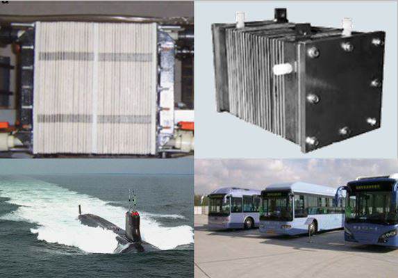 Figure 7. Clockwise from left: PEM Electrolyzers, PEM Electrolyzer stack, Electrolyzers for military and self-containing applications (in this case, the O2 is produced to provide breathable air), China Bus program used Spectracarb carbon paper for fuel cells.
Using Carbon Paper & Panels as Cathode-side Current Collectors
LINQCELL GDL1500 are optimum for use as Cathode (Hydrogen Side) Current Collectors in PEM Electrolyzers. Unlike the standard thin/low density Gas Diffusion Layers (GDL) that are intended mainly for PEM and PAFC fuel cells, the Spectracarb Porous Graphite Engineered Panel Family has been specifically engineered for the special requirements of PEM electrolyzers. Features include thicker structures from 1.5 to over 4 millimeters, and densities up to 0.95 g/cm3. These panels also have controlled compressibility to support the external forces from the assembly. In addition to several standard grades, these engineered panels can be made on a laboratory, prototype or production scale to meet specific customer requirements.
Watch our presentation on PEM electrolyzers as current collectors, in Hannover Messe 2016.
Please note that Spectracarb has since been discontinued and replaced by the much more efficient LINQCELL product series below:
| Product | Thickness | Thickness (mm) | Density (g/cm3) | Basis weight (g/m2) | Through-Plane Resistance (mΩcm2) | Through-Plane Resistivity (mΩcm) | Voltage Loss (mV) |
|---|---|---|---|---|---|---|---|
| LINQCELL GDL 1500 | 0.059" | 1.5 | 0.60 | 858 | 13.32 | 90.6 | 24.3 |
| LINQCELL GDL 1500B | 0.059" | 1.5 | 0.60 | 670 | 21 | 140 | 39 |
| LINQCELL GDL 1850 | 0.072" | 1.85 | 0.85 | 1562 | 13.18 | 70.5 | 25.5 |
| LINQCELL GDL 2200 | 0.086" | 2.2 | 0.6 | 1550 | 17 | 110 | 35 |
| LINQCELL GDL 2900 | 0.011" | 2.9 | 0.60 | 1734 | 24.57 | 87.7 | 27.6 |
All values are indicative and subject to tolerance