Solder Spheres
SnPb, In, BiSn and Lead-Free Solder Spheres
-
Home

-
Products
-
Soldering Materials
- Solder Spheres
Solder Spheres
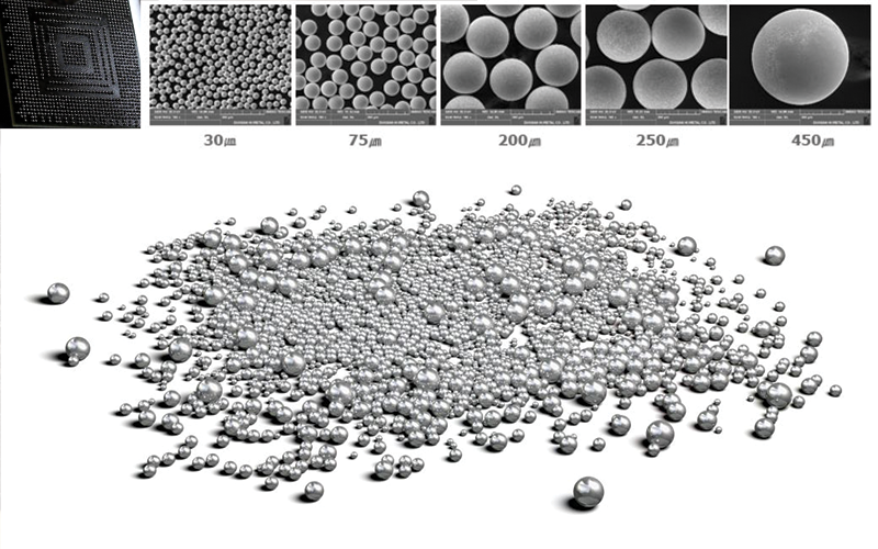
Solder spheres, commonly know as solder balls are the most common way to electrically interconnect flip chip semiconductors. CSPs , BGAS, LBGA are all arrays with small size factor that don't use bonding wires but use solder spheres beneath the package to aid with the miniaturization of the integrated circuits. Solder spheres come in multiple diamteres ranging from 0.075mm to 0.9mm and can fit in many package designs. There are multiple solder sphere alloys that can prove more or less reliable and can melt on a variety of temperatures. Normal spheres have a solidus (still solid) and a liquidus (liquid) temp with a gel like structure in between to aid with the bonding process. Eutectic solder spheres on the other hand have a very precise temperature where they switch from solid to liquid. This can help with tightly designed processes with very strict temperature requirements.
After many years of testing and debating, and with specific exceptions, the semiconductor industry has largely settled on the use of Tin (Sn), Silver(Ag), Copper(Cu) - or SAC - alloy for the assembly of lead-free products. Although the SAC alloy has been settled, which SAC alloy to use is still up for debate. North American and Europe manufacturers favor SAC305 (Sn3.0Ag0.5Cu), while Asian manufacturers generally favor SAC405 (Sn3.8Ag0.8Cu).
Whether you call them solder spheres or solder balls, CAPLINQ has been the premium supplier of solder balls since 2004. While many companies may offer solder spheres, very few companies offer the breadth and selection that CAPLINQ offers. Whether you are looking for eutectic Tin-Lead (SnPb) solder, high lead solder or lead-free variations, including Tin-Ag-Copper (SAC), Bismuth/Tin (BiSn), pure Tin (Sn), pure Indium (In) CAPLINQ has got you covered. We also offer low minimum order quantities and custom grades. Can't find the solder ball alloy you need? Let us know and we'll help you out.
-
 From
From
$72.83
LINQALLOY Bi57Sn42Ag1 | Near-Eutectic Pbfree Solder Spheres
- Leadfree Solder Spheres
- 1% Agg adds mechanical strength to bismuth-tin alloy
- Low-temperature near-eutetic Solder
- In stock
-

SACQ | Pb-free Solder Spheres
- Leadfree Solder Spheres
- Excellent Solder Joint Reliability for small devices
- Excellent fatigue resistance
- 8 weeks
-
 From
From
$72.83 Bi58Sn42 | Eutectic Pbfree Solder Spheres
- Leadfree Solder Spheres
- Lowest Cost Eutectic (138°C) Solder
- Low-Temperature Eutectic Solder
- In stock
-
 From
From
$769.23 CC-SAC305 | Copper Core SAC 305 Solder spheres
- SAC 305 alloy
- Core of the sphere is Copper
- Excellent fatigue resistance
- 8 weeks
-
 From
From
$471.57 In100 | Pure Indium Solder Spheres
- 100% Pure Indium Solder Spheres
- Soldering to non-metals
- Low Eutectic Melting temperature
- 6 weeks
-
 From
From
$36.36 SAC105 | Pb-free Solder Spheres
- Pb-free Solder Spheres
- Lowest cost Sn/Ag/Cu Alloy
- Excellent Fatigue Resistance
- 8 weeks
-
 From
From
$36.36 SAC125N | PbFree Solder Spheres
- Lead-Free Solder Spheres
- Lowest cost Sn/Ag/Cu Alloy
- Nickel Dopped, hence the SACNi name
- In stock
-
 From
From
$41.82 SAC305 | Pb-free Solder Spheres
- Leadfree Solder Spheres
- Lowest cost Sn/Ag/Cu Alloy
- Excellent Fatigue Resistance
- In stock
-

SAC387 | Pb-free Solder Spheres
- Pb-free Solder Spheres
- For BGA and CSP components
- Tin/Silver/Copper alloys
- 6 weeks
-
 From
From
$72.83 SAC396 | Pb-free Solder Spheres
- Pb-free Solder Spheres
- Excellent Solder Joint Reliability
- Best Wetting Sn/Ag/Cu Alloy
- In stock
-
 From
From
$41.82 SAC405 | Pb-free Solder Spheres
- Pb-free Solder Spheres
- Excellent Solder Joint Reliability
- Best Wetting Sn/Ag/Cu Alloy
- In stock
-
 Solder Spheres")
Sn100 | Pure Tin (4N) Solder Spheres
- Pure Tin
- Most important application electroplating
- Proven choice for coating of package leads and terminals
-
No longer available
-

Sn10Pb90 | High melting point Solder Spheres
- Medium Solidus/Liquidus transition
- High Liquidus temperature (301°C)
- Ideal for automotive applications
- 6 weeks
-
 From
From
$81.67 Sn5Pb95 | High melting point Solder Spheres
- Low Solidus/Liquidus transition
- High Liquidus point (322°C)
- Ideal for automotive applications
- 6 weeks
-
 From
From
$55.83 Sn63Pb37 | Eutectic Solder Spheres
- Eutectic Solder Spheres
- Tin lead
- For BGA and CSP components
- In stock
-
 From
From
$121.42 Sn96.5Ag3.5 | Eutectic Pbfree Solder Spheres
- Leadfree Solder Spheres
- Eutectic Melting Temp of 221°C (430°F)
- The highest Joint Reliability
- In stock
Product Selector Guide
| Alloy Type |
Tin-Lead/ Pb-free |
% Metal Loading | Melting Temperature | Remarks | |||||||
|---|---|---|---|---|---|---|---|---|---|---|---|
| Tin (Sn) % |
Lead (Pb) % |
Bismuth (Bi) % |
Silver (Ag) % |
Copper (Cu) % |
Indium (In) % |
Eutectic (°C) |
Solidus (°C) |
Liquidus (°C) |
|||
| Sn63Pb37 | Tin-Lead | 63 | 37 | - | - | - | - | 183 | - | - | Eutectic Solder Spheres |
| SAC105 | Pb-free | 98.5 | - | - | 1.0 | 0.5 | - | - | 220 | 225 | Pb-free Solder Spheres |
| SAC125N | Pb-free | 98.3 | - | - | 1.2 | 0.5 | - | - | 217 | 219 | 0.05% Nickel (Also called SAC125Ni) |
| SAC305 | Pb-free | 96.5 | - | - | 3.0 | 0.5 | - | - | 217 | 221 | Industry Standard Pb-free |
| SAC387 | Pb-free | 95.5 | - | - | 3.8 | 0.7 | - | - | 217 | 219 | Special Application Pb-free |
| SAC396 | Pb-free | 95.5 | - | - | 3.9 | 0.6 | - | - | 217 | 221 | Industry Standard Pb-free |
| SAC405 | Pb-free | 95.5 | - | - | 4.0 | 0.5 | - | - | 217 | 225 | Highest Silver Content |
| SACQ | Pb-free | 92.45 | - | 3 | 4 | 0.5 | - | - | 216 | 211 | |
| Sn96.5Ag3.5 | Pb-free | 96.5 | - | - | 3.5 | - | - | 221 | - | - | Eutectic Leadfree High Silver |
| Sn100 | Pb-free | 99.9928% min | - | - | - | - | - | 232 | - | - | 4N Pure Tin (>99.9928% Sn) |
| Bi58Sn42 | Pb-free | 42 | - | 58 | - | - | - | 138 | - | - | Eutectic Low-Temp Bismuth-Tin |
| Bi57Sn42Ag1 | Pb-free | 42 | - | 57 | 1.0 | - | - | - | 139 | 140 | Near-Eutectic Low-Temp Bismuth-Tin |
| Sn5Pb95 | Tin-Lead | 5 | 95 | - | - | - | - | - | 312 | 322 | High melting point Solder Spheres |
| In100 | Pb-free | - | - | - | - | - | 100 | 156.6 | - | - | Pure Indium Solder Spheres In100 |
| Sn10Pb90 | Tin-Lead | 10 | 90 | - | - | - | - | - | 268 | 301 | High melting point Solder Spheres |
| Sn96.5Ag3.5 | Pb-free | 96.5 | - | - | 3.5 | - | - | 221 | - | - | Eutectic Pb-free Solder Spheres |
Low volume flexibility, high volume pricing
CAPLINQ maintains an inventory of many sphere alloys and sizes, and we specialize in the fulfillment of small orders. CAPLINQ also offers volume breaks and discounts for our higher volume customers. A complete list of sphere diameters, packaging quantities, volume breaks and discounts can be seen by clicking on the product Alloy Type below
Frequently Asked Questions
Frequently Asked Questions about Solder Spheres
What\'s the difference between solder spheres and solder balls?
There is no difference between solder balls or solder spheres. Because solder balls do not sound very high tech and balls do not technically have a tolerance, the industry moved to the naming convention of solder spheres. Solder spheres are now more common and solder sphere diameter, diameter tolerances and sphericity information can now be measured and defined.
Why are the jumps in price breaks so high?
Solder spheres ultimately end up being made-to-order products with a limited shelf-life once produced. Furthermore, there is a lot of "start-up material" that is wasted at the beginning of each production, whether it is for 1 jar or 1000 jars. These wastes are calculated into the lower volume pricing and is the reason the price jumps are as high as they are.
What is the tolerance of your solder spheres?
The tolerance of the solder sphere depends on the size of the sphere. It can generally be summarized as 1.5% of the solder diameter. A more complete answer on the solder sphere tolerance can be found here.
What is the steps for solder spheres Reballing?
Refer to the Operation Manual of the Reballing guide here.
What size solder sphere defines whether it is for BGA, CSP or FlipChip?
There are no hard and fast rules for this, though generally, as solder spheres get smaller, they are used from BGAs to CSPs to Flipchip devices. Typically, it can be said that BGA solder balls are greater than 0.250mm in diameter and bigger, CSP are between 0.100mm and 0.250mm in diameter and flip chips use solder balls that are 0.100mm and under in diameter.
What is the shelf-life of solder spheres in tape and reel packaging?
The guaranteed shelf-life of solder spheres in tape and reel packaging is 1 year from the date of manufacture. There are simply too many variables to be able to account for all the possible scenarios of long term storage of the solder spheres in the tape and reel. In the jars, the solder spheres are preserved in an inert gas (nitrogen). In the tape & reel, the spheres are no longer in the inert gas, but are vacuum sealed, removing air from the individual package
The reason for the shelf-life is to limit the liability during the period in which we have a 100% confidence that the solder spheres have not oxidized. This confidence decreases as the time increases and the storage conditions are unknown.
To the best of our knowledge, the risk of oxidation when the reels are kept in cool, dry conditions are minimum, even for several months (or maybe even years) after the published shelf-life. We cannot officially increase the shelf-life without having scientific data to support this, but we do not believe there is any negative consequence to using the solder spheres beyond the published shelf-life date.
What is the work life of Solder Spheres?
For the solder sphere we don't spell out the work life in the Datasheet, because the alloys used in solder spheres are formulated to resist oxidation at room temperature. This means they won't significantly degrade just by being exposed to air after opening the container. Common practice is to mention the shelf life and storage conditions to maintain the optimal performance of the solder spheres. The product should be stored in sealed containers and should not be refrigerated. Probing of spheres in jars with fingers or other implements can damage the material by changing its shape or scoring the sphere surface or by contaminating the material. This could result in sphere placement difficulties.
Can I store solder spheres back to the jar?
Generally, we don't recommend putting unused spheres back into the original jar to avoid any potential contamination. Even with careful handling, there's a risk of introducing contaminants like skin oils, dust, or moisture into the jar when putting spheres back. This can affect the solderability of the spheres. We typically recommend using a complete jar at a time. Solder spheres are packaged in a nitrogen atmosphere to minimize oxidation. Opening and closing the jar can displace some of the nitrogen, potentially increasing the oxidation rate of the remaining spheres. You could use a separate moisture proof container to store your unused spheres.
Learn More
Solder Spheres for interconnection in Integrated circuit (IC) packages
Solder Spheres are primarily used in electronic packaging to create reliable electrical connections between components, particularly in high-density, high-performance applications. The selection of solder sphere size, material, and placement is crucial for the performance and reliability of these electronic devices. Proper design, manufacturing, and assembly processes are essential to ensure the quality of solder sphere connections. Here are some of the most common applications that utilize solder spheres for interconnection in IC packages:
Types of Ball Grid Array (BGA) packages:
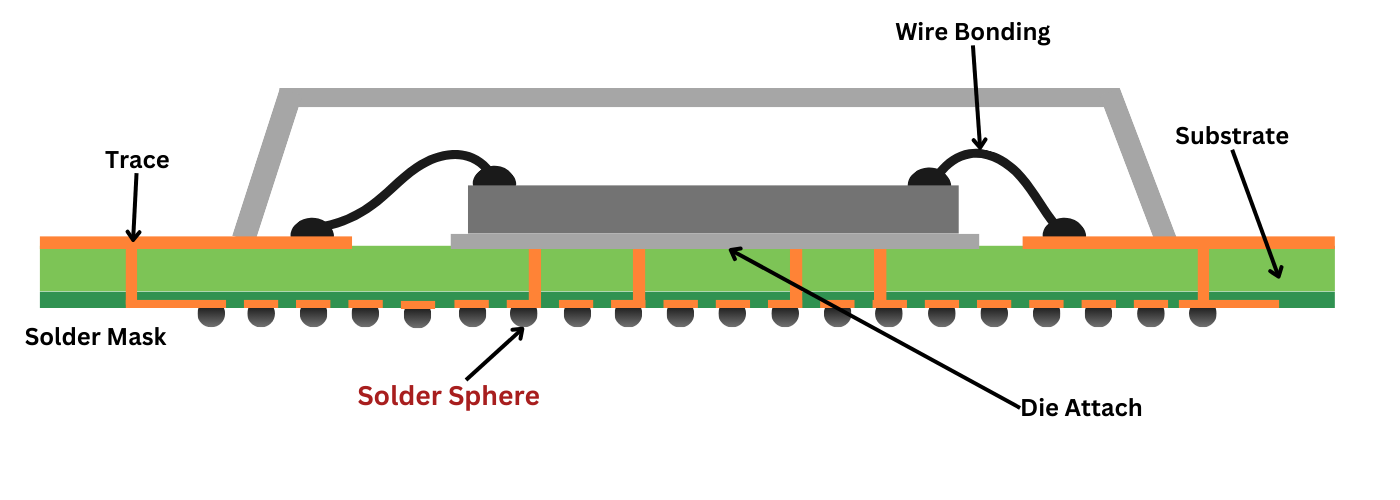
Plastic Ball Grid Array (PBGA): The most common type, offering a balance of cost and performance. The solder spheres connect the plastic-encapsulated IC to the PCB.
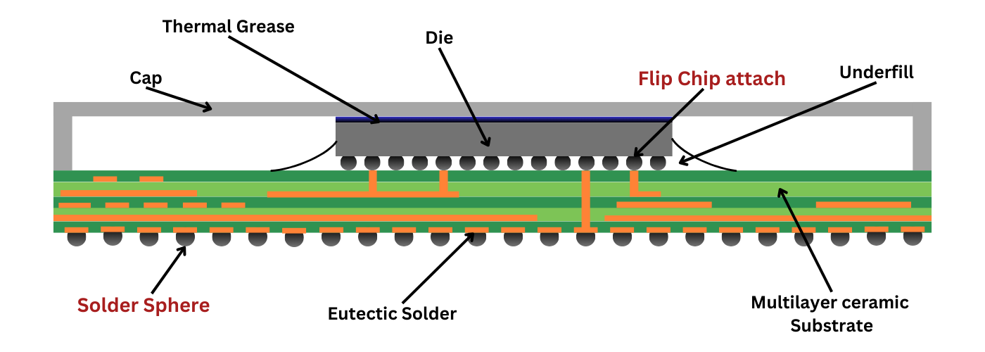
Ceramic Ball Grid Array (CBGA):Offers superior thermal performance and reliability. Utilizing solder spheres to establish connections between the ceramic substrate and the PCB.
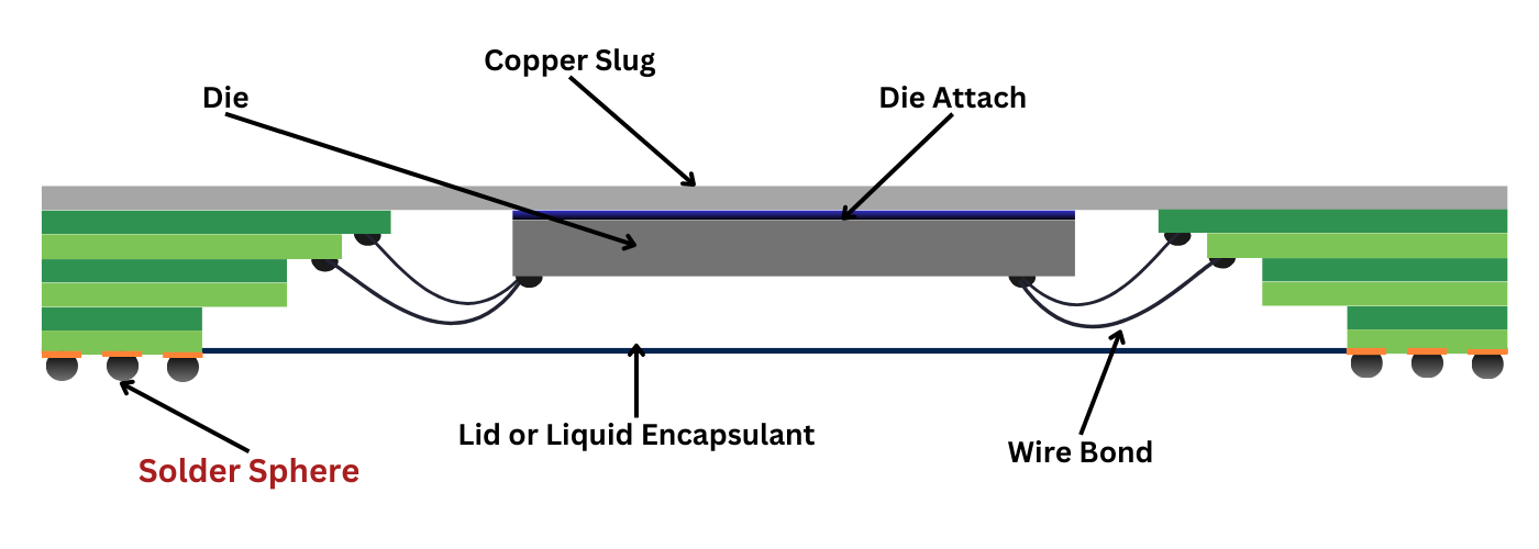
Cavity Ball Grid Array (CBGA): Improves thermal performance balance and reduces the overall package height. Employing solder spheres for electrical interconnections within a cavity structure.
Tape Ball Grid Array (TBGA): Thin and flexible package, suitable for space-constrained applications. Where solder spheres facilitate electrical connections between the tape-based package and the PCB.
Flip-Chip Ball Grid Array (FBGA): High-performance package with direct chip-to-package connection. Using solder spheres to connect the die directly to the PCB, eliminates the need for bond wires.
Micro BGA: Very small BGA package, often used in mobile devices and wearable electronics. Micro BGAs are a smaller version of standard BGAs. While typical BGAs have a ball spacing of 1.0mm or 0.8mm, micro BGAs have a much tighter pitch of around 0.4mm or less.

2. Chip-Scale Packages (CSP)
CSPs are smaller and thinner than traditional packages, and solder balls enable high-density interconnections in a limited space.
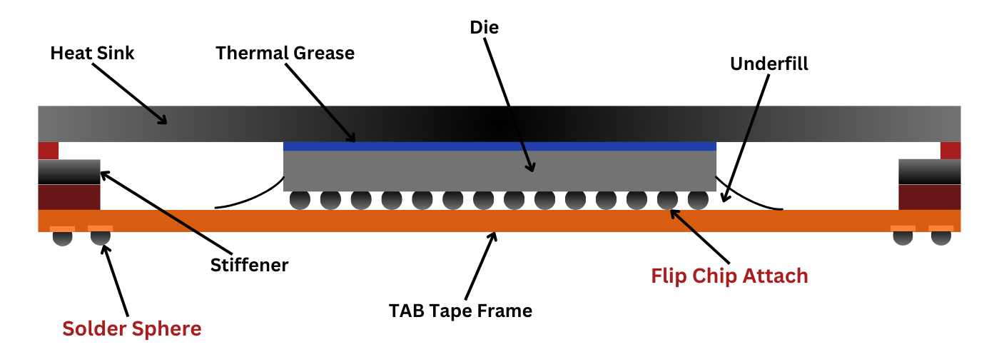
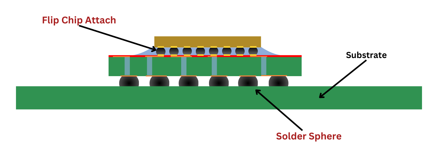
3. Flip-Chip Packages
A Flip Chip Package is a high-performance package where the integrated circuit (IC) chip is directly flipped and attached to the substrate using solder spheres. This direct connection eliminates the need for bond wires, resulting in improved electrical performance, smaller package sizes, and increased I/O density.
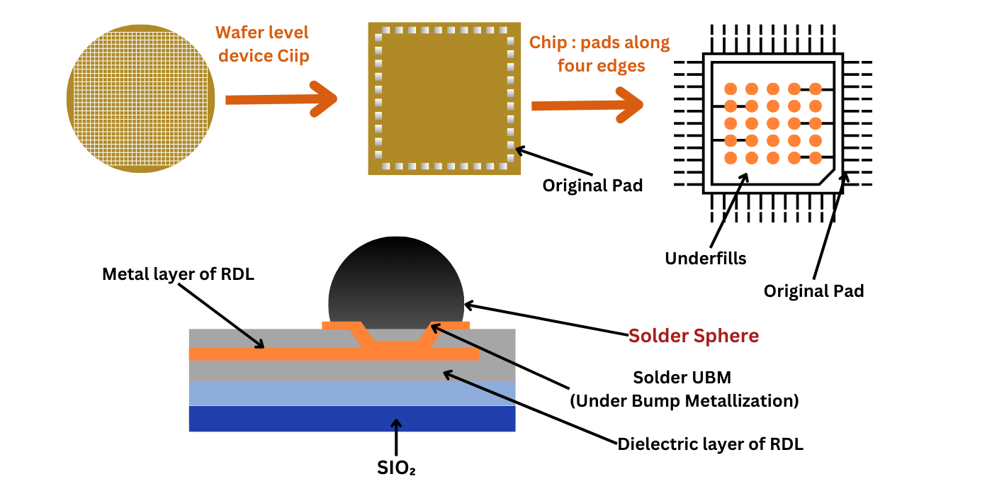
4. Wafer-Level Chip-Scale Packages (WLCSPs)
Wafer Level Chip Scale Package (WLCSP) is a type of package where individual chips are diced directly from a silicon wafer and encapsulated in a very small package. Solder spheres are used to connect the chip to the package substrate, enabling high-density integration and improved electrical performance.
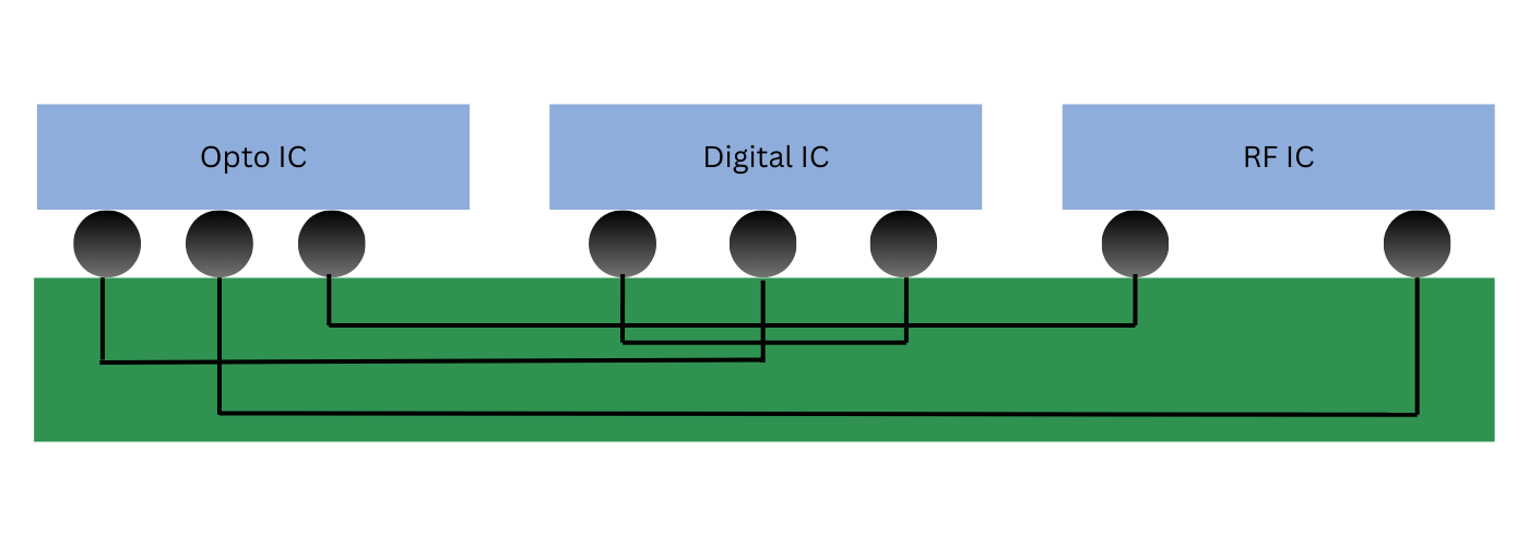
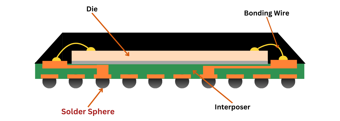
5. Multi-Chip Modules (MCMs)
Multi-Chip Modules (MCMs) integrate multiple IC dies onto a single substrate, enabling higher levels of system integration and performance. Solder spheres are used to connect these multiple dies to the substrate, as well as to connect the MCM to the external circuit board, providing high-density interconnections and improved electrical performance.
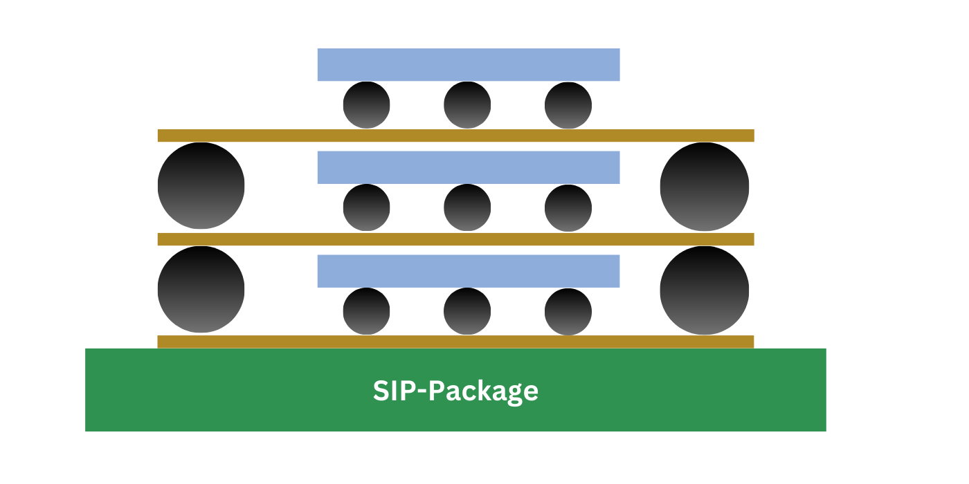
6. System-in-Package (SiP) Modules
System in Package (SiP) integrates multiple ICs and passive components into a single package. Solder spheres are used to connect these components to the package substrate, enabling high-density integration and improved electrical performance.
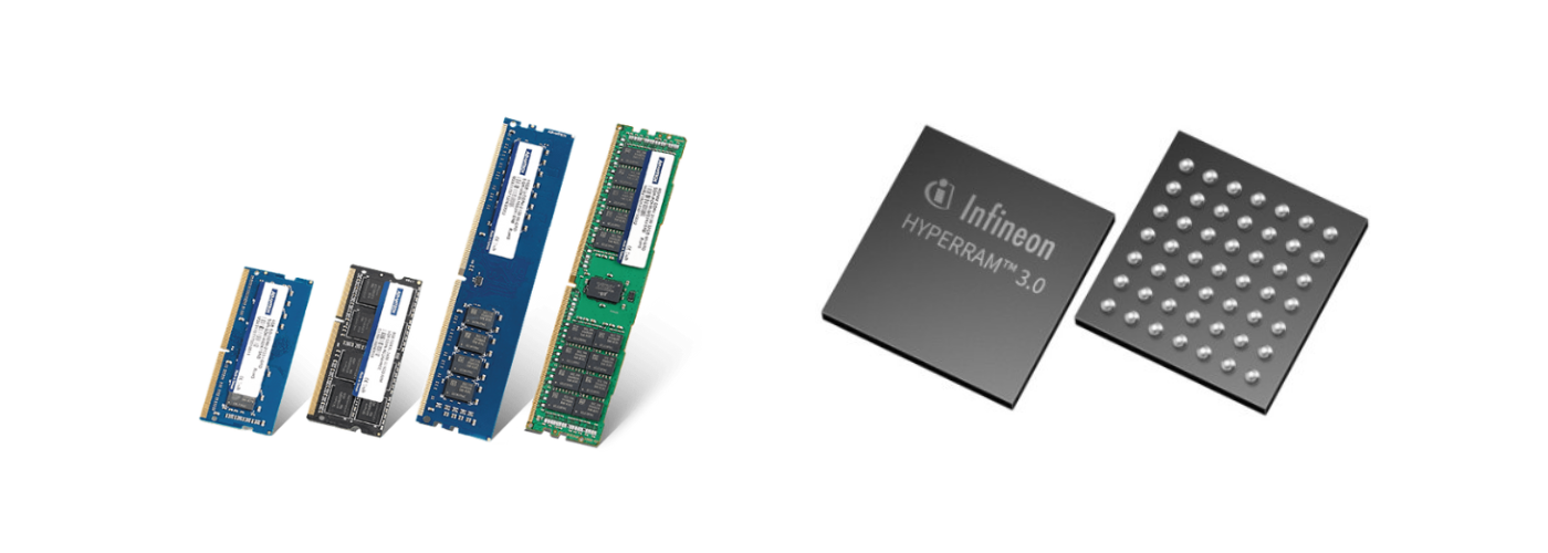
7. Memory Modules
Memory modules, such as DDR4 and DDR5, often use BGA packages to connect to the motherboard. Solder spheres on the underside of the module enable high-speed data transfer and reliable electrical connections.
8. High-Speed Interconnect Boards
High-speed interconnect boards require low-inductance connections to minimize signal degradation. Solder spheres can provide these low-inductance connections, improving signal integrity and reducing crosstalk.
Guiding Principles for Solder Sphere Selection
The selection of solder sphere size is a critical factor in the design and manufacturing of electronic assemblies. The ideal solder spheres size ensures optimal electrical connectivity, mechanical reliability, and thermal performance. Here are some key guiding principles:
1. Solder Alloy Composition:
When selecting solder spheres, several key factors must be considered. Firstly, the solder alloy composition is crucial. The melting point should be compatible with the reflow soldering process and the desired temperature profile. The alloy should also possess adequate strength and ductility to withstand mechanical stress during assembly and operation. Good thermal conductivity is essential for efficient heat dissipation, especially in high-power applications. Lastly, the solder alloy should exhibit good reliability, including resistance to thermal cycling, vibration, and corrosion.
2. Solder Spheres Size and Pitch:
The size and pitch of the solder spheres should be compatible with the package design, including the die size, I/O count, and pitch of the land pattern. The solder sphere size and pitch should be chosen to achieve the desired interconnect density. Additionally, the solder spheres size and pitch can influence the thermal performance of the package. Smaller solder spheres can provide higher interconnect density but may compromise thermal performance.
3. Solder Spheres Placement Accuracy:
Precise placement of the solder spheres is critical to ensure reliable electrical connections. The solder spheres should be coplanar to avoid excessive stress during reflow soldering. Solder spheres coplanarity refers to the uniformity of the solder spheres heights relative to a reference plane, typically the seating plane of the package. Coplanarity inspection requires 3-D inspection techniques that use either a laser or interferometry to measure the geometries of the BGA and the solder spheres.
4. Solder spheres Surface Finish:
The solder spheres surface should be free of excessive oxidation to ensure good solderability. The solder spheres should also be free of contaminants that could adversely affect the soldering process.
5. Thermal Management
The size of solder spheres is crucial for both high-power and low-power devices. For high-power devices, larger solder spheres are preferred as they can dissipate heat more efficiently, reducing the risk of thermal stress and improving reliability. In contrast, smaller solder spheres may be sufficient for lower power applications, as they can still provide adequate thermal performance without compromising on cost or space.
6. Mechanical Reliability:
The size of solder spheres also plays a role in the mechanical reliability of the assembly. Larger solder spheres can provide better mechanical strength and resistance to vibration and shock. However, in fine-pitch applications where high density is required, smaller solder spheres may be necessary. In such cases, careful design and assembly are crucial to ensure the reliability of the solder joints.
7. Manufacturing Process Capabilities:
The stencil design and printing process must be capable of accurately dispensing solder paste with the desired sphere size. The size of the solder sphere is directly related to the amount of solder paste required. Smaller solder spheres require less solder paste, while larger solder spheres require more. Therefore, the stencil design must be optimized to accommodate the specific size of the solder spheres being used. Additionally, the reflow profile must be optimized to ensure proper melting, wetting, and solidification of the solder spheres.
Key Types of Solder Ball Placement Machines:
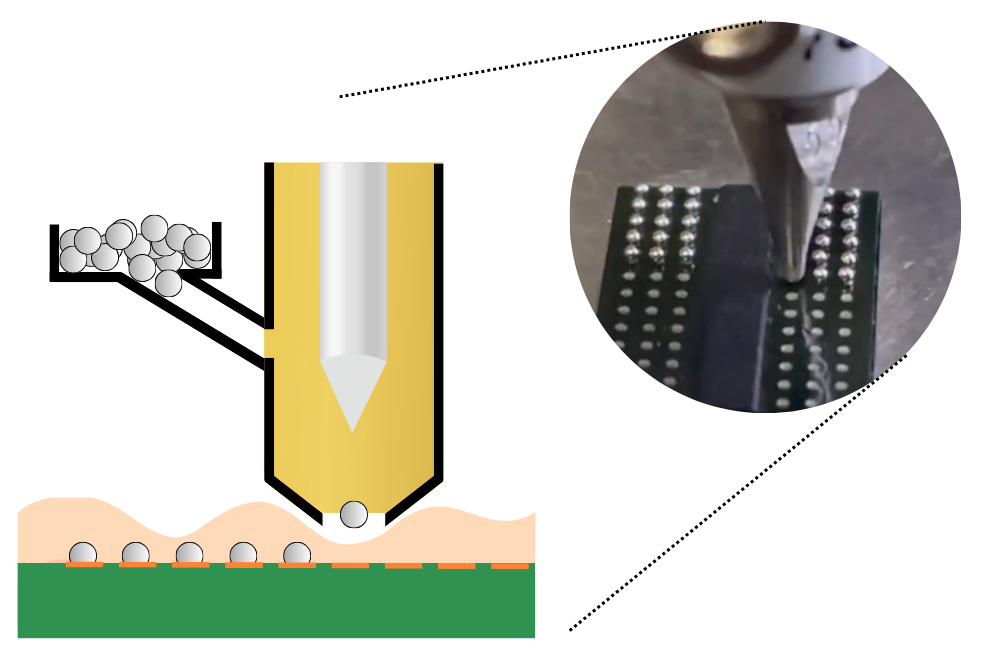
1. Dispensing-Type Machines:
Dispensing-type machines utilize a precise system to place individual solder spheresonto a substrate. While this method offers high accuracy and flexibility for various ball sizes and patterns, it suffers from lower throughput compared to other techniques. Laser solder ball jetting technology is an alternative approach that addresses these limitations. This method employs a laser to melt solder paste, which is then ejected in precise droplets onto the substrate. By eliminating the need for mechanical dispensing, laser jetting enables higher throughput and finer control over solder spheres placement.
2. Stencil-based Machines:
Stencil-based solder spheres dispensing machines utilize a stencil with apertures to define the placement pattern of solder spheres. Solder paste containing solder spheres is dispensed through the stencil onto the substrate, enabling high-throughput and good accuracy for large-scale production. However, this method is less flexible for custom patterns and smaller ball sizes.

3. Wafer-Level Ball Placement Machines:
Wafer-level ball placement machines are specifically designed for placing solder spheres on wafer-level packages. These machines offer high precision and high throughput for wafer-level manufacturing. However, they require specialized equipment for wafer handling and alignment, limiting their flexibility and increasing the cost of operation.

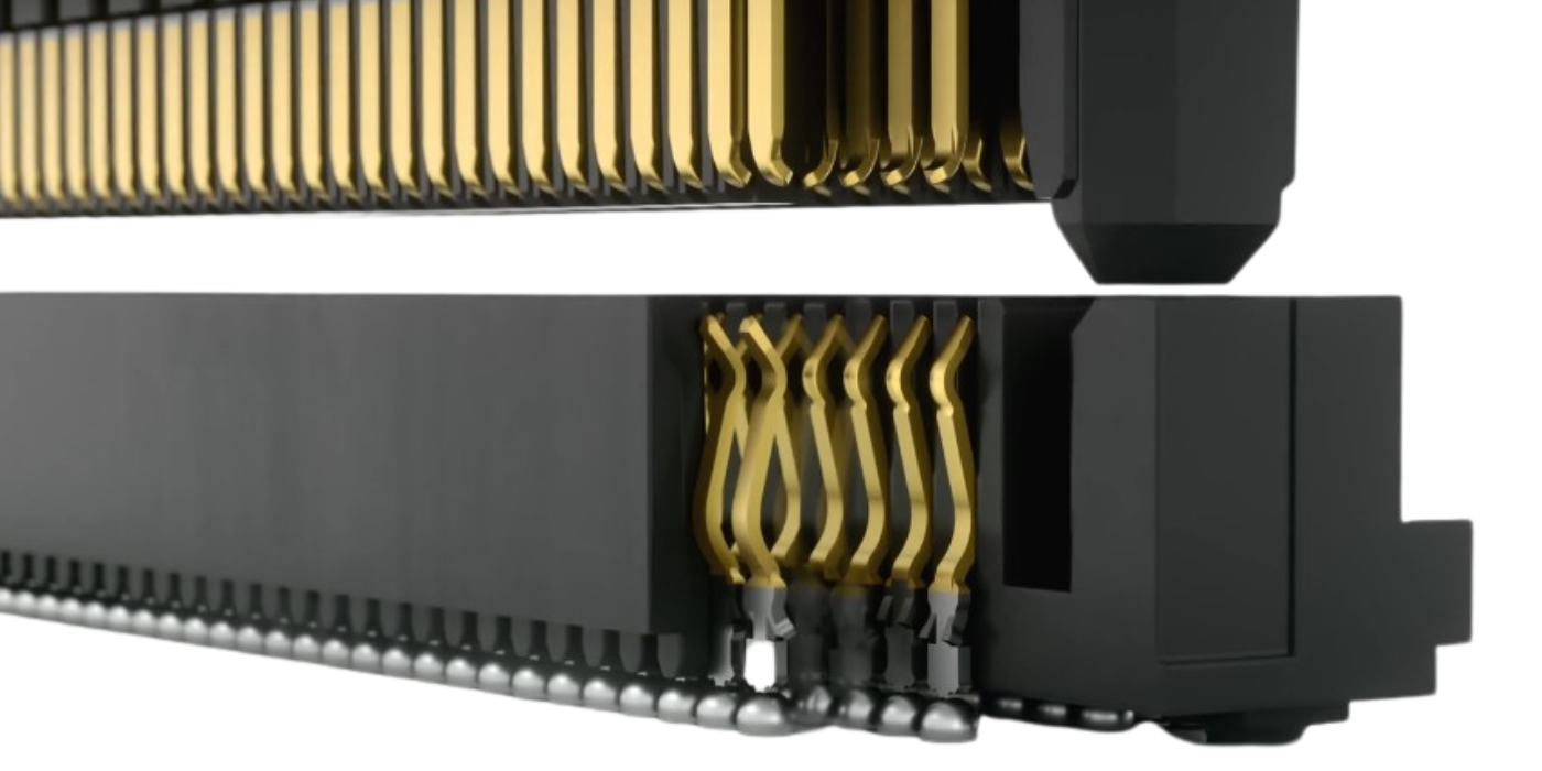
Array packaging moved semiconductor packages from wire bonding to solder balls
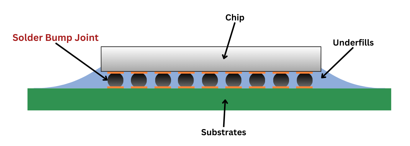
When you are using all four sides and even stacking wafers what can you do to further increase the number of inputs and outputs? The answer turned out to be: use the bottom of the chip as well. So, instead of many small thin legs, solder spheres would be placed directly on the bottom of the chip and would act as the connection between the Ball Grid Array (BGA) and the circuit board. This meant full encapsulation in an epoxy molding compound was no longer necessary and you could simply use an underfill.
250,000 solder spheres: sounds like a lot, but at micron sizes, that’s just enough for a heaped tablespoon full. Eventually, solder spheres got smaller and smaller so that they could pack even tighter grids of connection on the bottom of silica die. In these flip chips setups, tiny solder spheres are used instead of even 25-micron thick gold wire. Solder spheres are made in an amazing process with incredible accuracy and tight quality control.
High Tech Tin
CAPLINQ is not only able to supply the alloys and purify the solder material, but it has an innovative diameter and spheroid selecting system of solder balls and an advanced anti-oxidation technology that actually dopes an anti-oxidation element into the alloy in addition to its OSP surface coating process.
Not only are our solder spheres High-Tech, but they are made from a unique uniform droplet spraying technology that far outperforms competitors in terms of productivity. This combination of high technology and high productivity allow CAPLINQ to offer its customers the best value for the best product.
| Solder ball diameter (mm) |
Variation |
Pitch size |
| 0.75 |
0.90 - 0.65 |
1.50, 1.27 |
| 0.60 |
0.70 -0.50 |
1.0 |
| 0.50 | 0.55 - 0.40 | 1.00, 0.80 |
| 0.45 | 0.50 - 0.40 | 1.00, 0.80, 0.75 |
| 0.40 | 0.45 - 0.35 | 0.80, 0.75, 0.65 |
| 0.30 | 0.35 - 0.25 | 0.80, 0.75, 0.65, 0.50 |
| 0.25 | 0.28 - 0.22 | 0.40 |
| 0.20 | 0.22 - 0.18 | 0.30 |
| 0.15 | 0.17 - 0.13 | 0.25 |
Presentations
Surface Mount Technology (SMT) Materials, Processing, and Troubleshooting
This presentation provides a comprehensive overview of surface mount technology (SMT), covering assembly materials, manufacturing processes, and common troubleshooting techniques. It reviews solder pastes, fluxes, adhesives, reflow profiles, defect analysis, and best practices for improving assembly quality, process consistency, and manufacturing yield.
Recommendation for PCB Assembly of BGA Using Copper Cored Solder Sphere
This presentation discusses best practices for assembling ball grid array (BGA) packages using copper-cored solder spheres. It examines the advantages of copper-cored solder technology, recommended PCB assembly processes, thermal profile considerations, and reliability improvements for high-performance electronic applications.
Optimizing Solder Sphere Performance
This presentation explores the factors that influence solder sphere performance in advanced electronic packaging. It reviews solder sphere materials, manufacturing quality, assembly processes, and reliability considerations, providing practical guidance for optimizing joint integrity, minimizing defects, and improving long-term performance in semiconductor and PCB applications.