Carbon Capture and Utilization
Green Energy Integration
- Home

- Renewable Energy
- Carbon Dioxide Electrolyzers
Carbon Dioxide Electrolyzers
Closing the Carbon Loop through CO2 Electrolysis
CO2 emissions continue to increase as several industries continue to depend on fossil fuels. The atmospheric CO2 concentration has almost doubled after the Industrial Revolution (Current: >400 ppm, before the Industrial Revolution: 280 ppm). This increase translated to a global temperature rise of approximately 2 °C. To reduce the adverse effects of global warming to human life and property, the Intergovernmental Panel on Climate Change (IPCC) limits greenhouse gas emissions in such a way that the global temperature rise will decrease to 1.5 °C. To achieve this goal, CO2 emissions must be reduced to half of their 2015 levels by 2030.
One effective way to reduce carbon emissions in industries is by combining heavy industrial processes with renewable energy. This approach requires efficient methods to capture CO2 from the air or other gas streams and convert it into valuable chemicals and fuels. The main techniques for carbon capture and utilization include biomass with carbon capture and storage (BECCs), CO2 hydrogenation using thermal activated catalysts, and CO2 electrolysis.
 | Bioenergy with carbon capture and storage (BECCS) is a technology that combines biomass energy production with CO2 sequestration to achieve net-negative emissions. Plants absorb CO2 as they grow, and when biomass is burned for energy, the CO2 released is offset by the carbon absorbed during growth, making the process carbon neutral. By capturing and storing the CO2, BECCS removes it from the atmosphere, creating a carbon-negative impact. As a scalable solution, BECCS could play a key role in reducing emissions. However, its commercial implementation requires huge land areas—potentially as much land as is currently used for global food production—which presents a significant challenge.
PROS: Can be carbon negative, scalable CONS: Large land required, high energy input for capturing and storing CO2 |
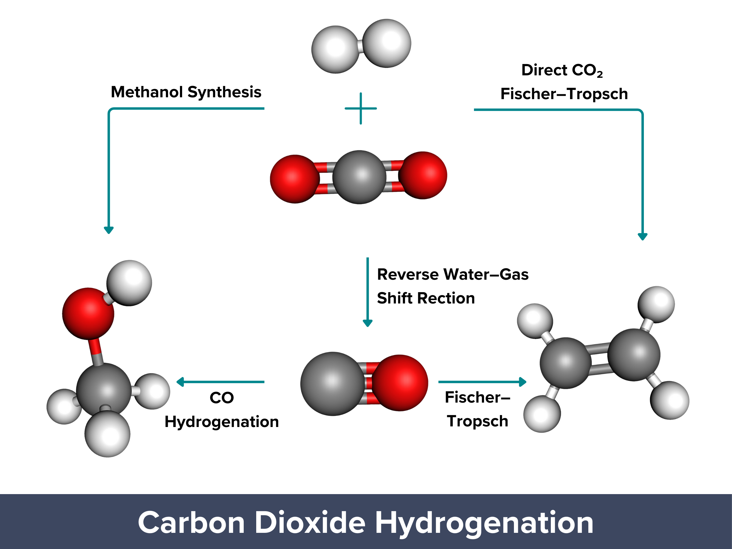
| CO2 hydrogenation, i.e. reacting CO2 with hydrogen gas, is a process that can convert emissions into useful chemicals and fuels. Now, the process can be carbon-neutral or even carbon-negative when renewable hydrogen gas is used. Initially, CO2 is converted into CO and water, a mixture called syngas, through the reverse water–gas shift (RWGS) reaction: CO2 + H2 → CO + H2O Syngas can then be further processed into liquid fuels through the Fischer–Tropsch synthesis (FTS) or converted into methanol through methanol synthesis: Fischer–Tropsch (for liquid fuels): CO + H2 → Liquid fuels + Water Methanol synthesis: CO + 2 H2 → Methanol (CH3OH) The Fischer–Tropsch and methanol synthesis reactions are useful for making fuels, but they need high temperatures and pressures, which uses a lot of energy. These processes can produce valuable fuels, but they are not very selective and require complicated catalysts, making them less efficient and more costly. PROS: Can produce carbon-neutral/negative products, useful for creating fuels/chemicals CONS: High temperatures and pressures needed, high energy demand, complex catalysts required |
 | Electrochemical CO2 reduction reaction (CO2R) turns CO2 into chemicals and fuels using only water and renewable electricity. If CO2 is captured from the air, CO2R can help close the carbon cycle. It produces chemicals like ethylene or methanol in one step, unlike traditional methods that require multiple reactions. CO2 electrolysis operates at lower temperatures and pressures, using renewable energy sources like solar or wind, making it more energy-efficient than conventional processes. It also has no moving parts, allowing easy separation of products and making it ideal for mass production and automated maintenance. These features make CO2R a scalable, sustainable, and potentially carbon-negative solution for reducing CO2 emissions. PROS: Operates under mild conditions, can be powered by renewable energy, scalable and low-cost, carbon-negative potential CONS: Energy efficiency may vary, still under development for large-scale deployment |
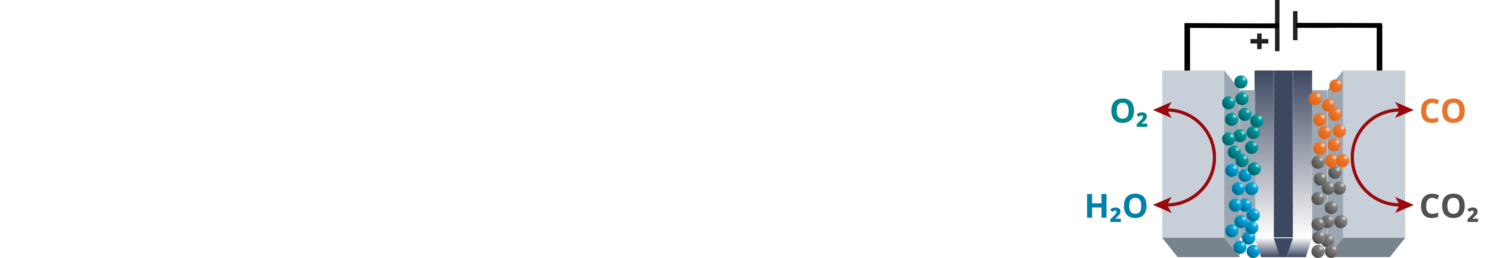
Key Processes involved in Electrochemical Carbon Dioxide Electrolysis
High Value-added Products from CO2 Electrolyzers
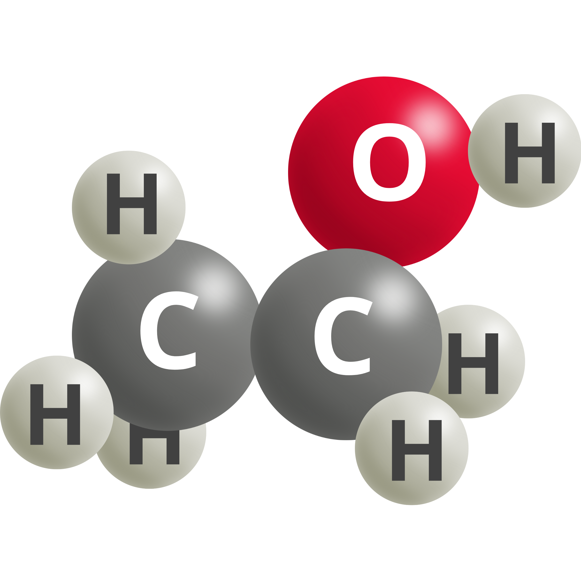
Depending on the energy input, operating and reaction conditions, and metal or alloy electrodes/catalysts employed, the electrolysis or electrochemical reduction of CO2 can generate different products, such as carbon monoxide (CO), formic acid (HCOOH), hydrocarbons like ethylene (C2H4), and alcohols (e.g. CH3OH).
| Product | Reaction | Reaction Potential [V vs. RHE] | |
 | Carbon Monoxide | CO2 (g) + 2 H+ + 2e– → CO + H2O | –0.10 |
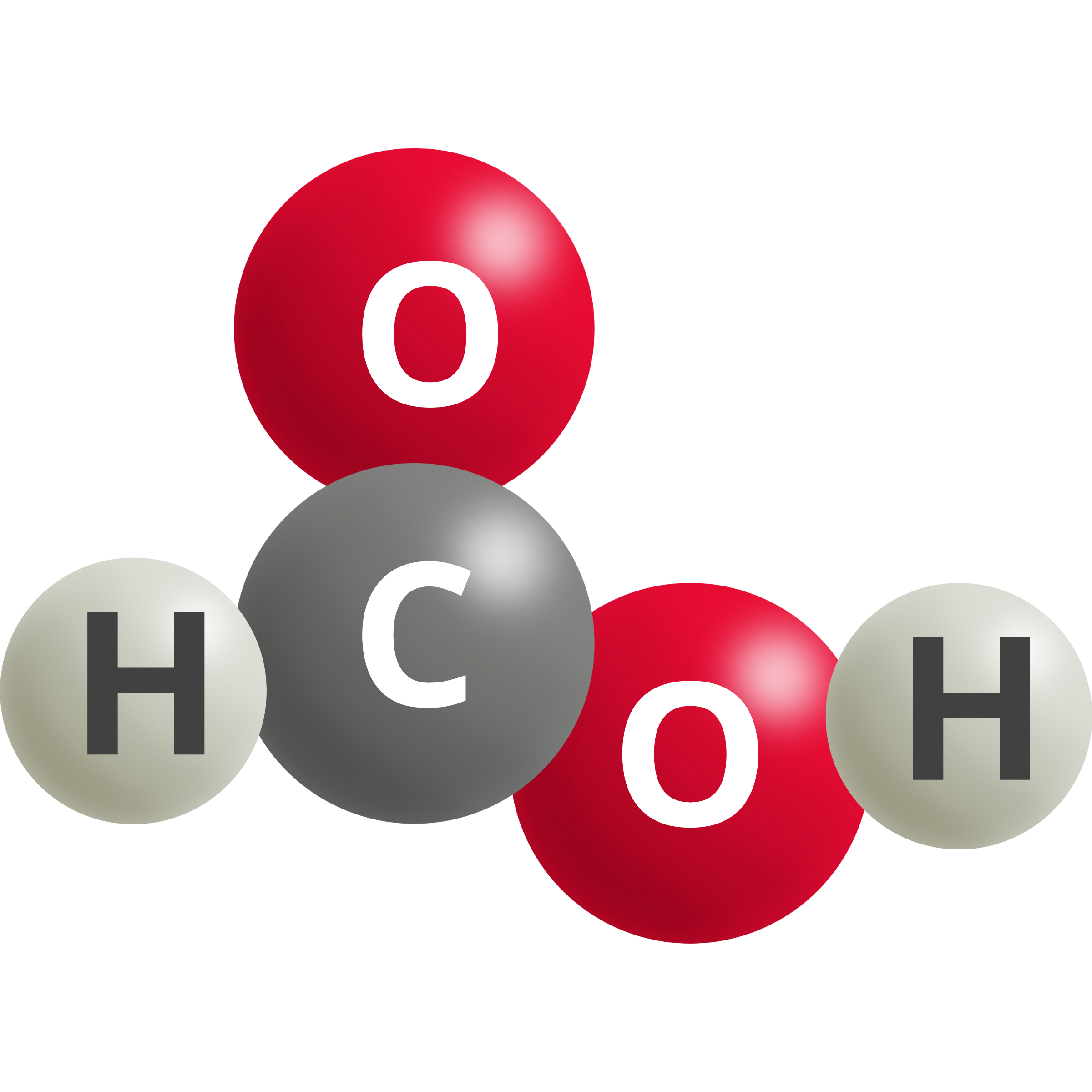 | Formic Acid | CO2 (g) + 2 H+ + 2e– → HCOOH | –0.12 |
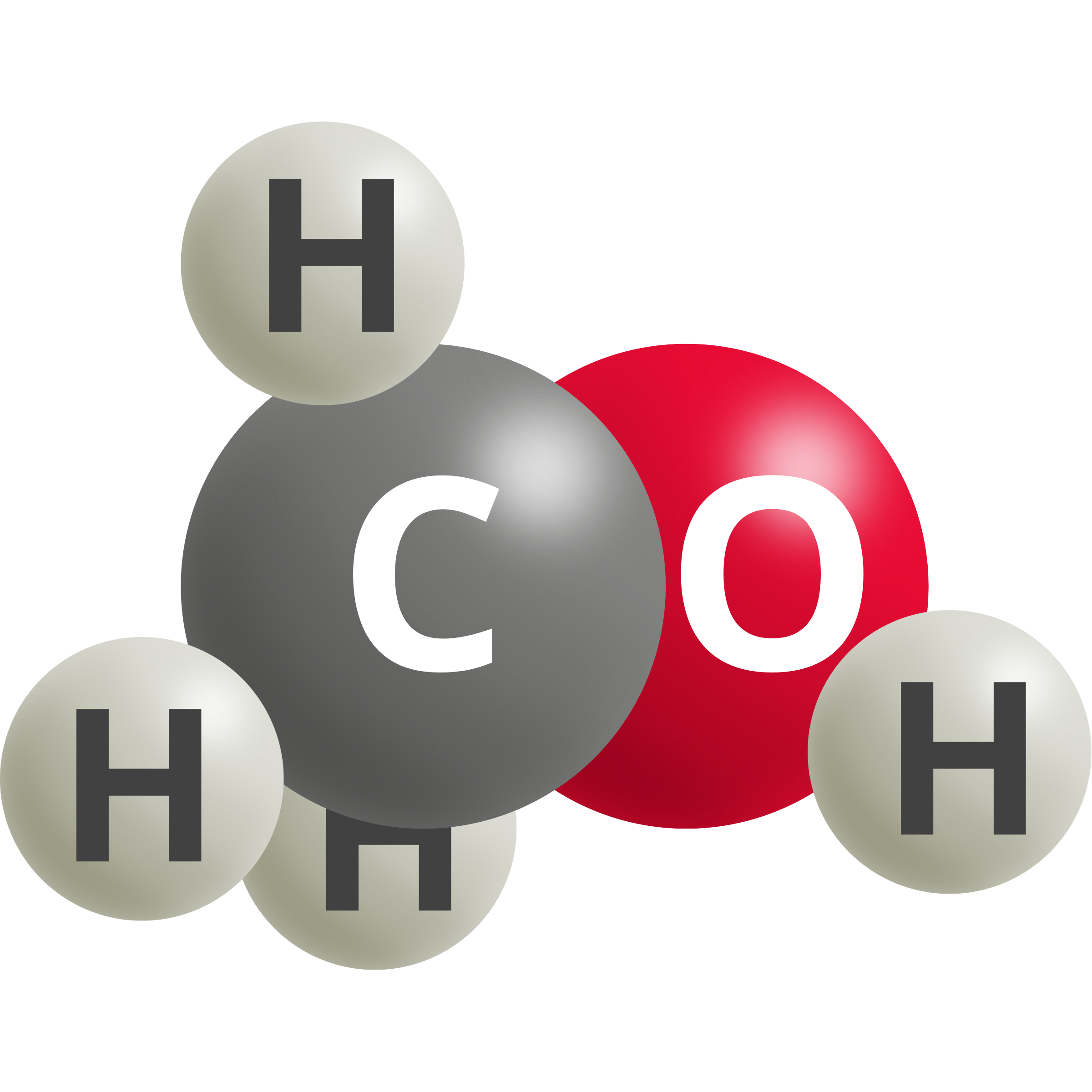 | Methanol | CO2 (g) + 6 H+ + 6e– → CH3OH + H2O | 0.03 |
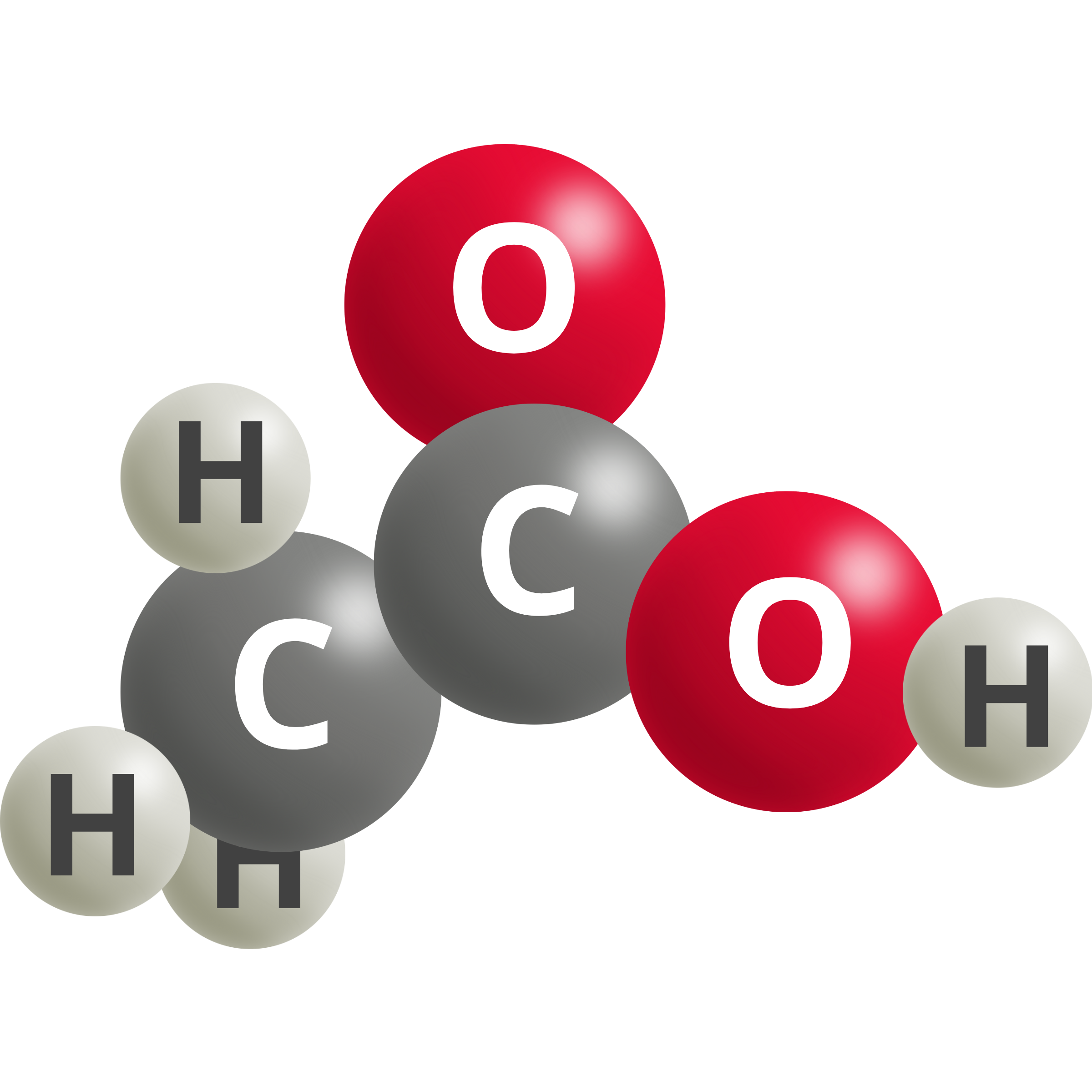 | Acetic Acid | 2 CO2 (g) + 8 H+ + 8e– → CH3COOH + H2O | 0.11 |
 | Acetaldehyde | 2 CO2 (g) + 10 H+ + 10e– → CH3CHO + 3 H2O | 0.06 |
 | Vinyl Alcohol | 2 CO2 (g) + 12 H+ + 12e– → C2H3OH + 3 H2O | 0.09 |
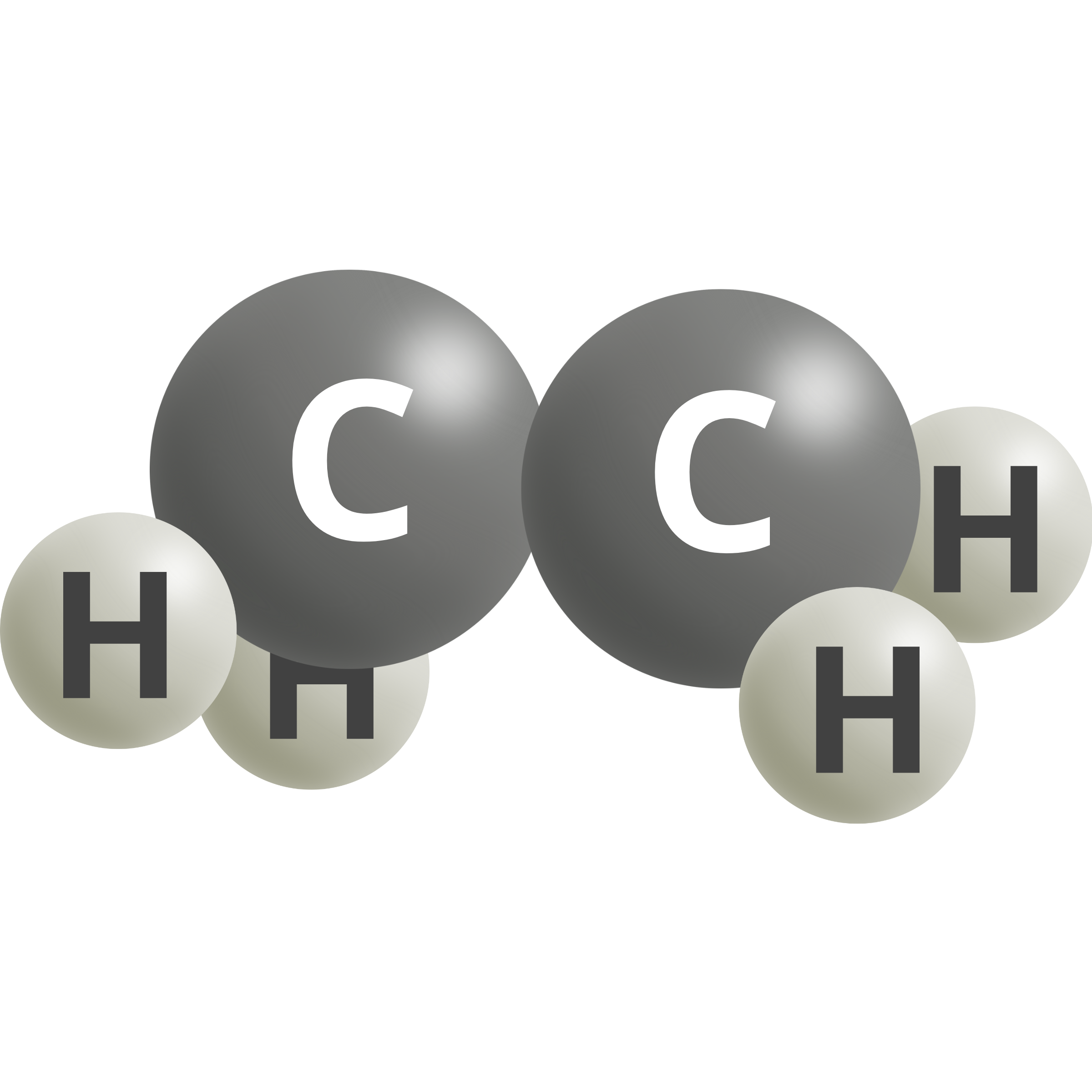 | Ethylene | 2 CO2 (g) + 12 H+ + 12e– → C2H4 + 4 H2O | 0.08 |
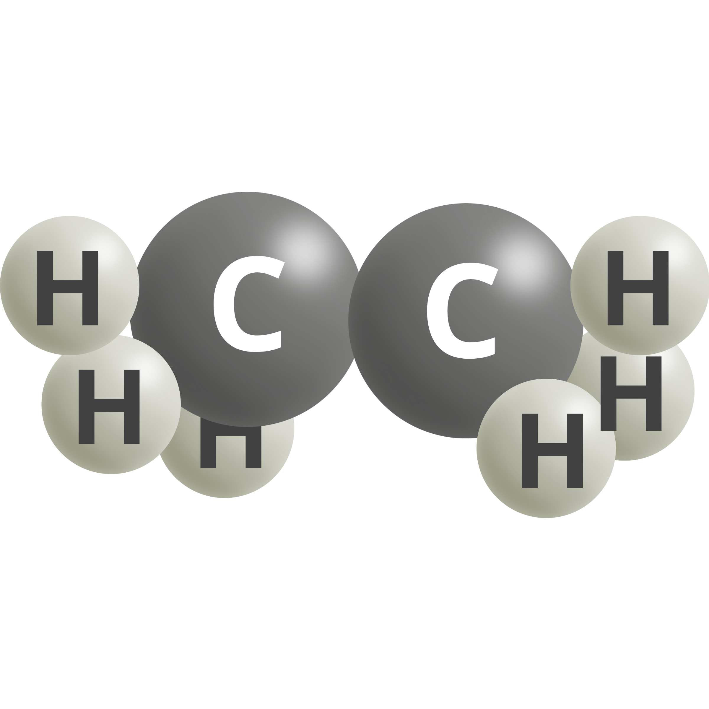 | Ethane | 2 CO2 (g) + 14 H+ + 14e– → C2H6 + 4 H2O | 0.14 |
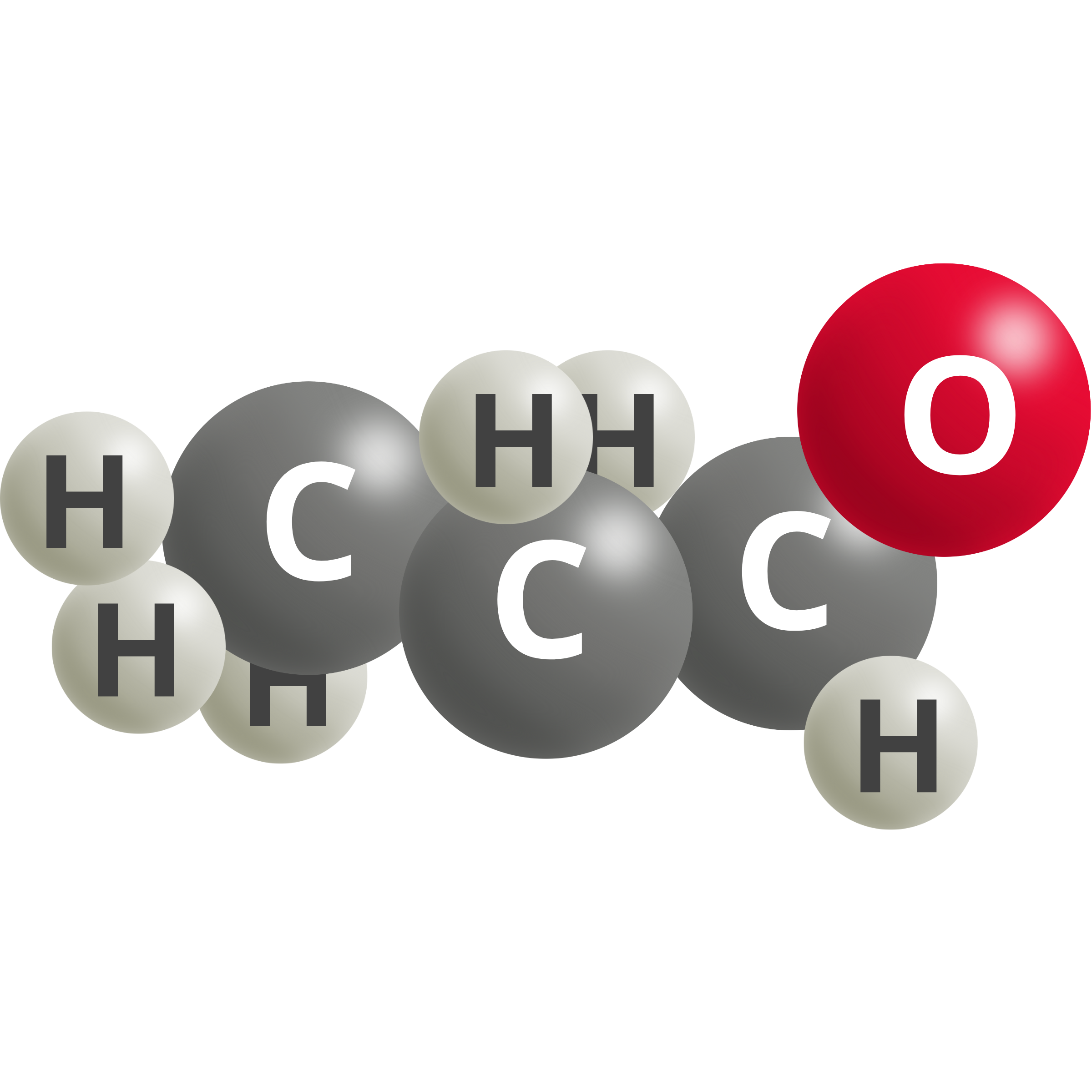 | N-propionaldehyde | 2 CO2 (g) + 16 H+ + 16e– → C2H5CHO + 4 H2O | 0.09 |
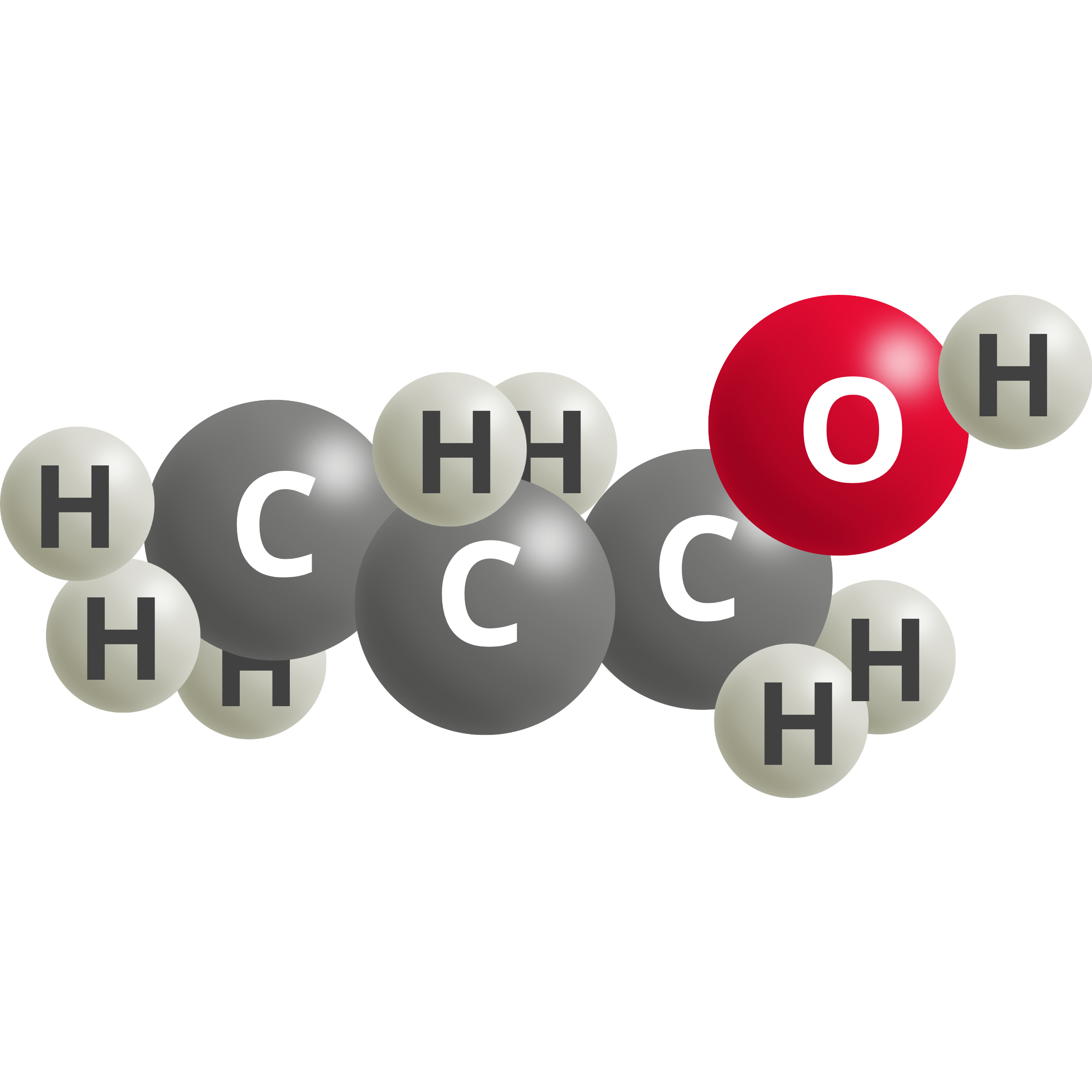 | Ethanol | 3 CO2 (g) + 18 H+ + 18e– → C2H5OH + 5 H2O | 0.10 |
Key Cell Designs for CO₂ Electrolysis: H-Cell, Flow Cell, and Membrane Electrode Assembly (MEA)
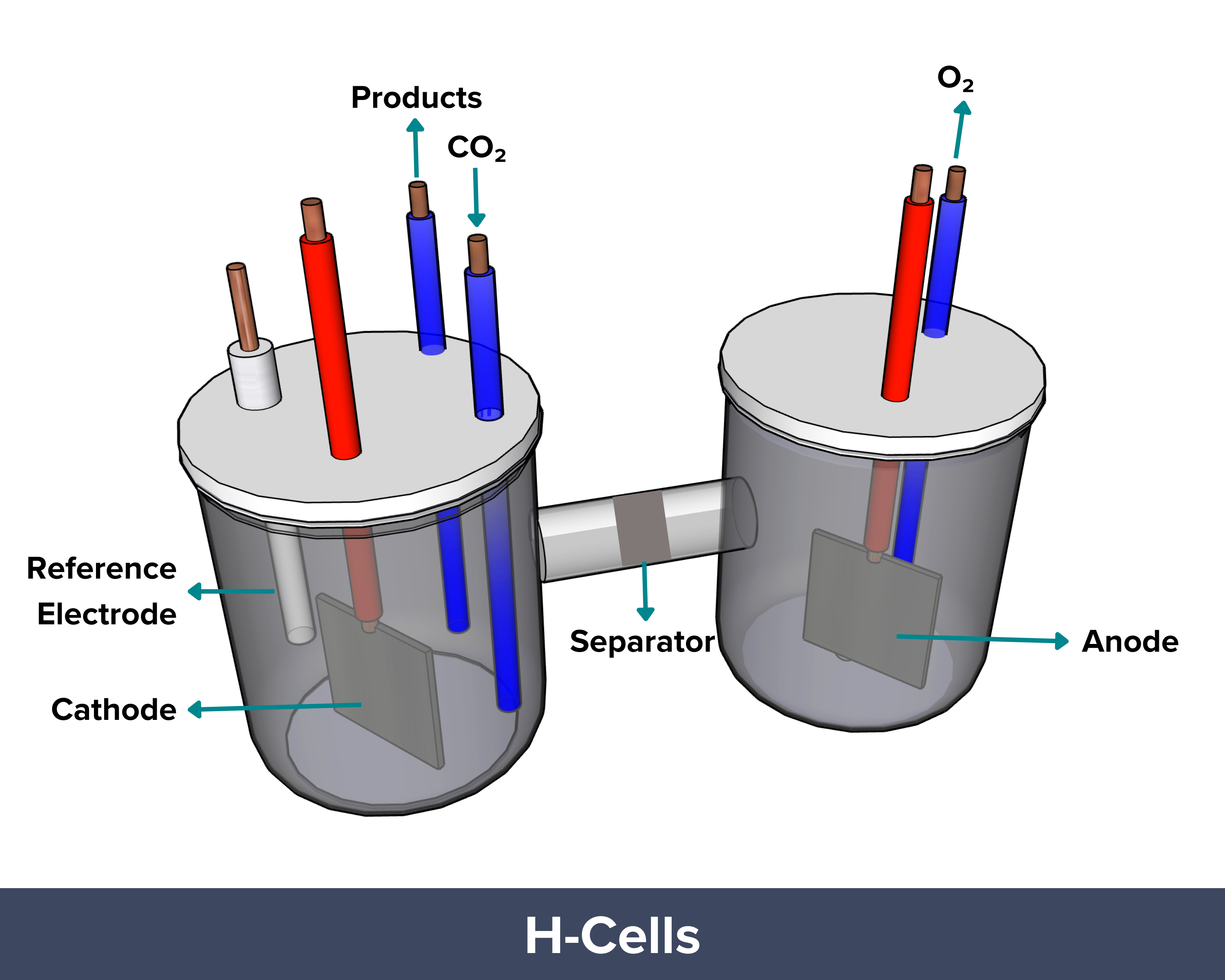 | H-cell electrolyzers are basic lab setups used to study how catalysts convert carbon dioxide into useful chemicals through electrochemical reactions. In this design, the cathode, or the site in which CO₂ is converted, is submerged in a liquid electrolyte. CO₂ gas first dissolves into the liquid before reaching the catalyst surface. CO2 has a low solubility in liquid (about 34 mM at room temperature). As such, only a small amount is available on the catalyst surface for the reaction at any point of time. This limits the current density (reaction rate) of the H-cell electrolyzer to <100 mA/cm², which is much lower than the requirement for commercial applications (>500 mA/cm²).
PROS: Low cost and easy to assemble, ideal for rapid lab-scale catalyst screening CONS: Low current density (<100 mA/cm²), Cannot be used for commercial CO2 conversion |
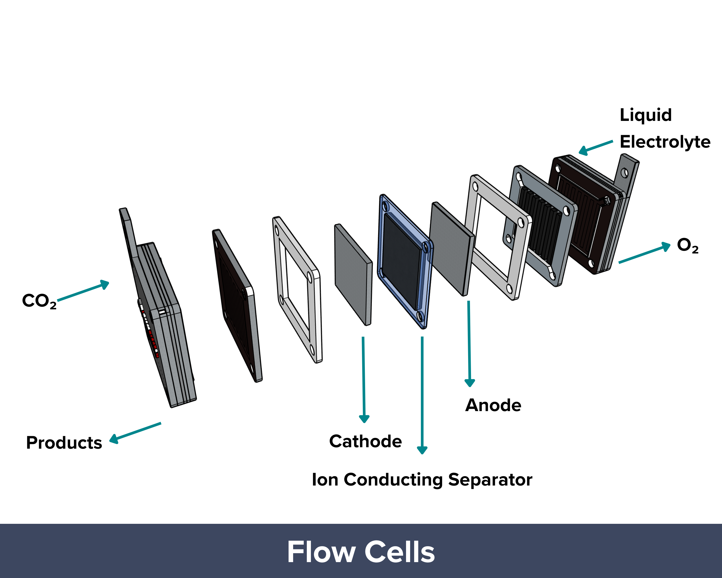
| Flow cell CO₂ electrolyzers are designed to achieve higher reaction rates (or current densities) than those of H-cells. In a flow cell, like in H-cells, the anode and cathode chambers are filled with liquid electrolytes with a porous separator or diaphragm in between. The difference is that gas diffusion electrodes are being used in flow cells. These GDEs aid in the delivery of the gaseous CO2 to the catalyst sites, effectively reducing the diffusion distance (“travel path”) to just 50 um to 50 nm. It helps overcome mass transport limitations and allows the system to reach industrially relevant current densities greater than 1 A/cm². To improve performance, concentrated alkaline electrolytes (10 M KOH) are used. The high pH prevents the occurrence of a competing hydrogen evolution reaction and supports the formation of valuable multi-carbon products like ethylene (C₂H₄) with high Faradaic efficiency. But this does not come without a caveat. The OH– ions from the very concentrated electrolyte react with the CO2 feed, forming carbonates and bicarbonates. This side reaction reduces conversion efficiency, meaning only a small fraction of the supplied CO₂ is converted into the desired product. PROS: Uses GDEs to shorten the travel path and deliver CO₂ more efficiently to the catalyst, High reaction rates and current densities (>1 A/cm²), Suitable for industrial applications CONS: High electrolyte alkalinity, Material and system durability challenges due to harsh pH conditions, CO₂ loss due to carbonate/bicarbonate formation |
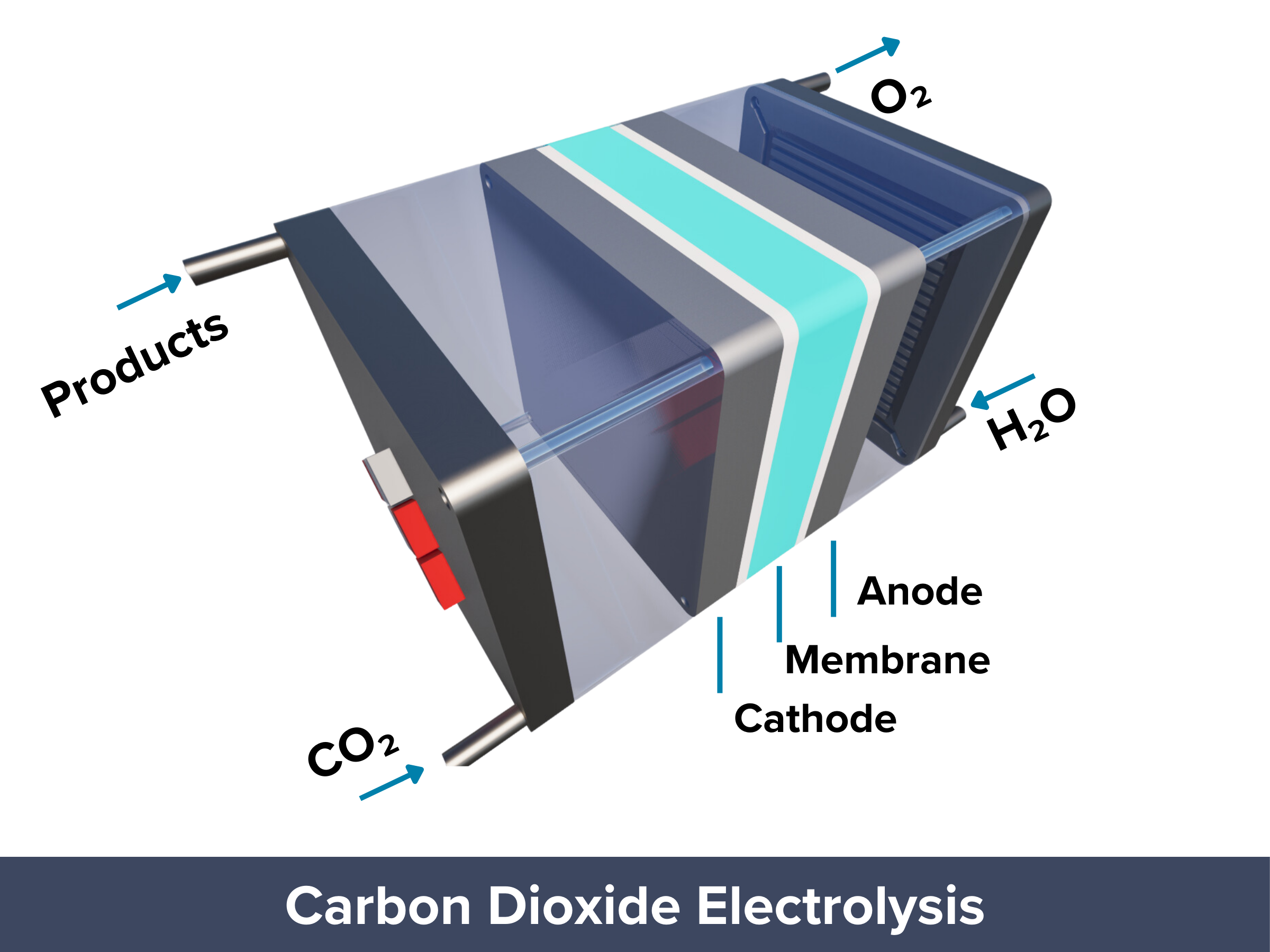
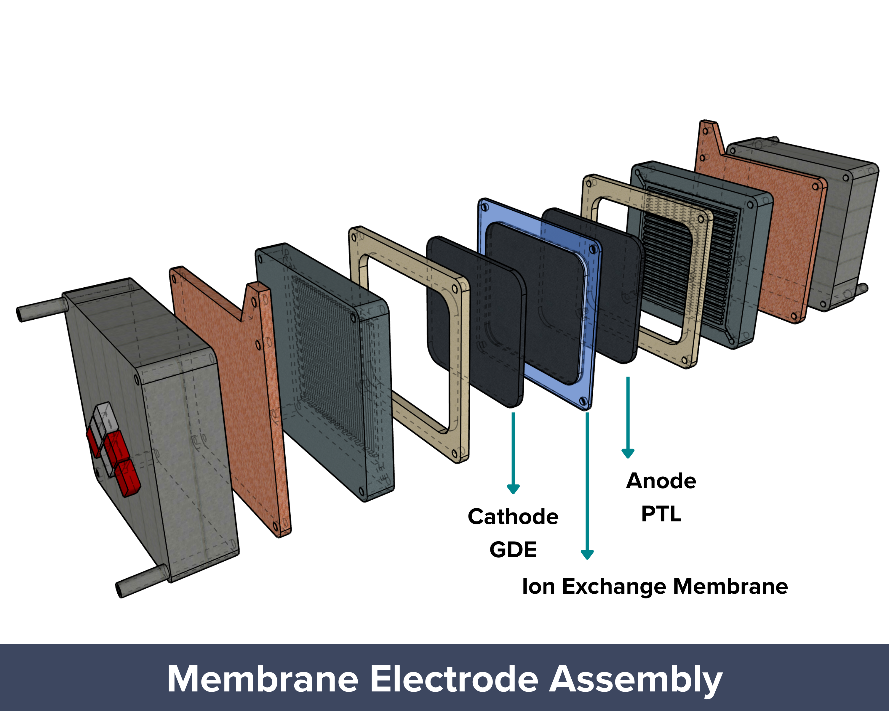 | The membrane electrode assembly (MEA), also known as the zero-gap design, has long been used in fuel cells and water electrolyzers and is now gaining attention for CO₂ electrolyzers. In this setup, the anode and cathode are separated by a polymer or ion exchange membrane that lets only specific ions pass through. This helps prevent unwanted mixing of products between the electrodes. The design also cuts down the diffusion distance significantly, since only a thin membrane (less than 100 µm) separates the electrodes, making it more efficient than H-cells or flow cells. Another key difference is how CO₂ is supplied. In MEA systems, humidified CO₂ gas is fed directly to the cathode, unlike in H-cells and flow cells where CO₂ is bubbled through a liquid electrolyte. Since CO₂ has low solubility in liquids, the direct gas feed in MEAs ensures a steady supply of CO₂ to the catalyst surface. With minimal gap between electrodes and continuous CO₂ delivery, mass transport limitations are minimized, allowing the system to reach high current densities. PROS: Proven design adapted from fuel cells and water electrolyzers, Thin membrane (<100 µm) minimizes diffusion distance between electrodes, Direct gas feed of humidified CO₂ to the cathode, Compact and efficient design with good scalability potential CONS: Membrane dehydration can occur if humidification isn’t properly controlled, Membrane cost and durability can be limiting factors for long-term or large-scale use |
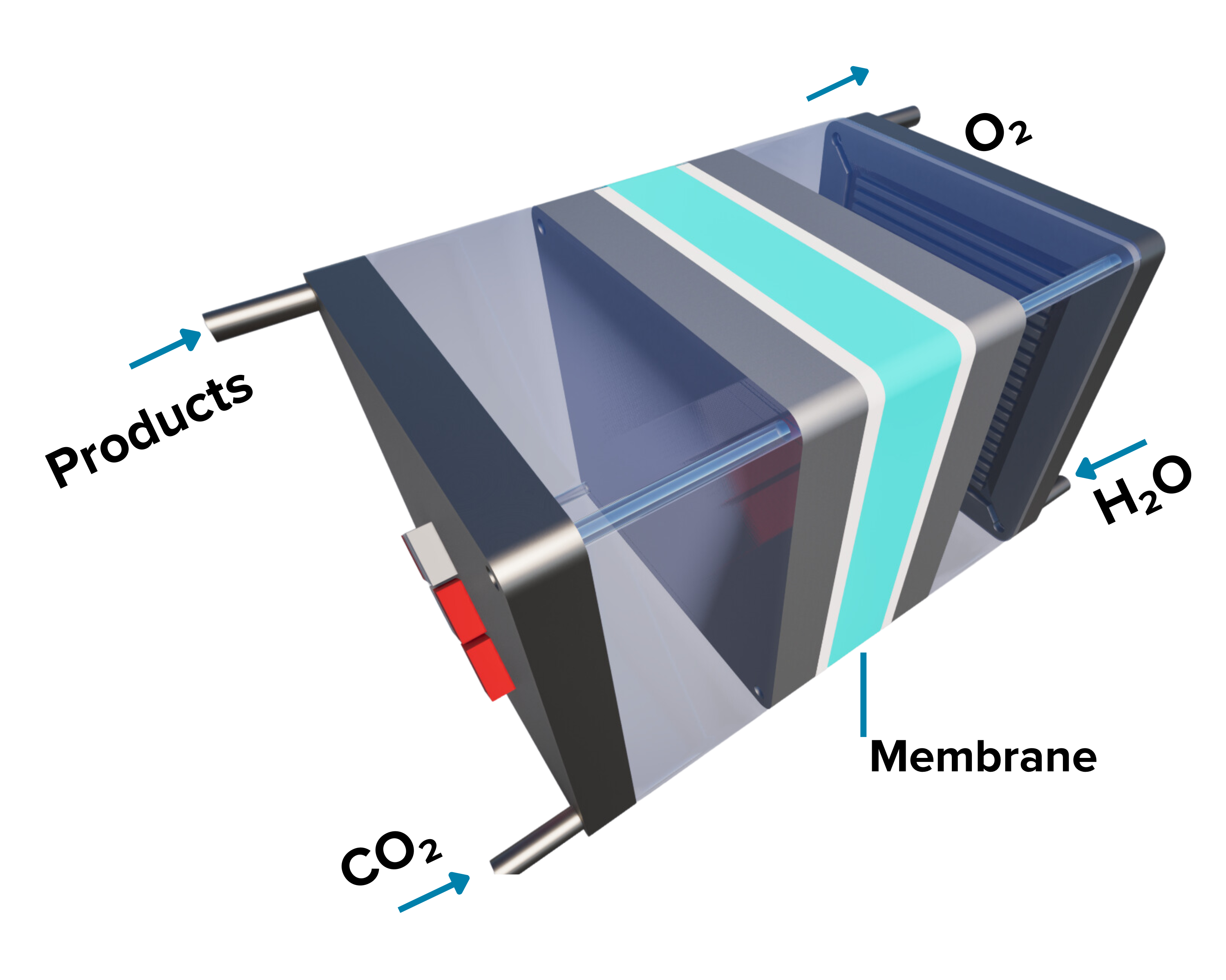
Inside a Membrane Electrode Assembly CO2 Electrolyzer
The zero-gap design and low-temperature operation of MEA electrolyzers are considered one of the most promising approaches for commercially viable CO₂ reduction (CO₂R) at an industrial scale.
To understand why this setup works so well, it helps to look at the main parts of an MEA CO₂ electrolyzer. Each layer, from the gas diffusion layer to the catalyst and membrane, plays an important role in how the system performs.
Ion Exchange Membranes
Read more about ion exchange membranes for electrochemical devices and carbon dioxide
Cathode Gas Diffusion Electrodes
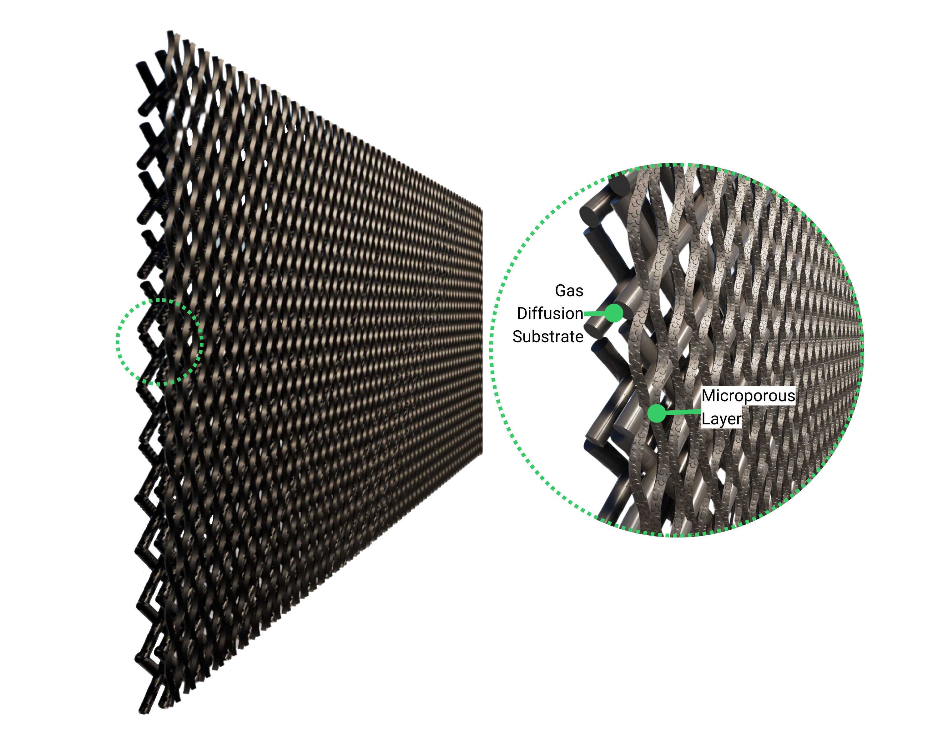
The catalyst layer contains materials active toward the carbon dioxide reduction reaction (CO₂RR), enabling the conversion of CO₂ into valuable products. GDEs ensure efficient CO₂ delivery, electron conduction, and reaction performance while managing gas and water transport across the electrode interface.
Read more about cathode gas diffusion electrodes for electrochemical devices and carbon dioxide
Frequently Asked Questions about Carbon Dioxide Electrolyzers
Efficiency varies based on factors such as the catalyst, operating conditions, and target product. Generally, the faradaic efficiency (the portion of current used to produce a specific product) ranges from 50% to 90% depending on these factors.
What is the typical operating temperature of a CO₂ electrolyzer?CO₂ electrolysis can occur across a range of temperatures, categorized as low-temperature electrolysis (LTE) and high-temperature electrolysis (HTE). LTE operates below 100 °C, while HTE can reach up to 600 °C, boosting reaction rates and energy efficiency, and making it suitable for producing complex hydrocarbons.
A few companies are developing commercial CO₂ electrolyzers, though the technology is still emerging, with most applications in pilot or early commercial phases.
How are CO₂ electrolyzers different from water electrolyzers?In water electrolysis, H₂O is split into hydrogen (H₂) and oxygen (O₂) gas at the cathode and anode, respectively.
In CO₂ electrolysis, CO₂ is reduced to form carbon-based products like CO, formic acid, methanol, or ethylene, depending on the catalyst and reaction conditions. CO₂ electrolysis involves multiple complex reactions with competing pathways, often producing a mix of products. It requires catalysts that can stabilize CO₂ intermediates and selectively promote the desired reduction pathways, making catalyst design and reaction control more challenging.
Presentations
Carbon Dioxide Electrolyzers
The presentation shown on the left is focused on explaining the fundamental principles involved ...
Materials for Carbon Dioxide Electrolyzers
This presentation shows CAPLINQ's solutions for improving the performance and durability of carbon dioxide electrolyzers through advanced materials and customized product offerings.