-
Home

-
Products
-
Electrochemical Materials
-
Ion Exchange Membranes & Polymers
- PEMION - PF1-HLF8-15
PEMION - PF1-HLF8-15

- PFAS-free Proton Exchange Membrane with Hydrocarbon reinforcement
- 15 µm thickness
- Optimized for heavy duty fuel cell applications
Product Description
Pemion® PF1-HLF8-15 represents a fundamental shift in the approach to proton exchange technology through its migration from perfluorosulfonic acid (PFSA) chemistry to hydrocarbon materials, providing substantially lower gas crossover and addressing PFAS-related environmental and end-of-life issues at considerably higher performance. Pemion® enables major efficiency and performance gains, while aligning with needs of the renewable economy. Pemion® PF1-HLF8-15 is designed for the very oxidative fuel-cell and water electrolyzer environment and is very stable in these conditions. PF1-HLF8-15 is a so-called "Super Acid", a very stable membrane in acidic conditions, as there are no known degradation pathway in acidic conditions for the membrane.
Pemion® PF1-HLF8-15 is the only environmentally friendly option on the market. We have identified that this material exceeds 40000 humidity cycles at OCV, significantly exceeding the US DOE targets of 20000. There are no protruding fibers on either side of the membrane. Both faces are smooth and flat.
For use in fuel cell applications including heavy duty transport & automotive, hydrocarbon based Pemion® membrane and ionomer offers several advantages over incumbent perfluorinated materials to increase the efficiency, versatility, and lifetime of fuel cell engines, including:
Key Features:
- Reduced gas solubility in the polymer decreases hydrogen and nitrogen crossover, reducing parasitic losses, minimizing chemical degradation, and extending the range and lifetime of both the membrane and catalyst.
- Produced on reinforcement at thicknesses competitive to leading PFSA membranes in the industry: Pemion® provides leading conductance and durability without compromise.
- High proton conductivity for additional gains to efficiency and power density
- Unlike PFSA materials, hydrocarbon Pemion™ polymers are chemically stable up to 200 °C, offering significantly greater temperature stability and enabling a development platform for other fuel cell components to meet industry operating targets of 120 °C.
- Hydrocarbon Pemion™ polymers allow for substantially easier end-of-life precious metal recovery, reducing costs and eliminating the significant environmental concerns associated with acidic perfluorinated compounds.
- Optimized for heavy duty fuel cell applications
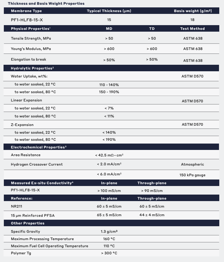
Technical Specifications
| General Properties | |||||
|
Specific Gravity
Specific Gravity
Specific gravity (SG) is the ratio of the density of a substance to the density of a reference substance; equivalently, it is the ratio of the mass of a substance to the mass of a reference substance for the same given volume. For liquids, the reference substance is almost always water (1), while for gases, it is air (1.18) at room temperature. Specific gravity is unitless. |
1.3 | ||||
|
Total Thickness
Total Thickness
Total thickness is taking into account all the films, coatings, adhesives, release liners and special layers and is the maximum thickness of a film or tape. |
15 μm | ||||
| Thermal Properties | |||||
|
Glass Transition Temperature (Tg)
Glass Transition Temperature (Tg)
The glass transition temperature for organic adhesives is a temperature region where the polymers change from glassy and brittle to soft and rubbery. Increasing the temperature further continues the softening process as the viscosity drops too. Temperatures between the glass transition temperature and below the decomposition point of the adhesive are the best region for bonding. The glass-transition temperature Tg of a material characterizes the range of temperatures over which this glass transition occurs. |
300 °C | ||||
| Mechanical Properties | |||||
|
Elongation
Elongation
Elongation is the process of lengthening something. It is a percentage that measures the initial, unstressed, length compared to the length of the material right before it breaks. It is commonly referred to as Ultimate Elongation or Tensile Elongation at break. |
50 % | ||||
|
|||||
| Chemical Properties | |||||
| Water Absorption | 95 - 140 % | ||||
| Physical Properties | |||||
| Young's modulus | 600 MPa | ||||
| Hydrolytic Properties | |||||
| Linear Expansion | 11 % | ||||
| Water Uptake | 170 % | ||||
| Z-Expansion | 190 % | ||||
Additional Information
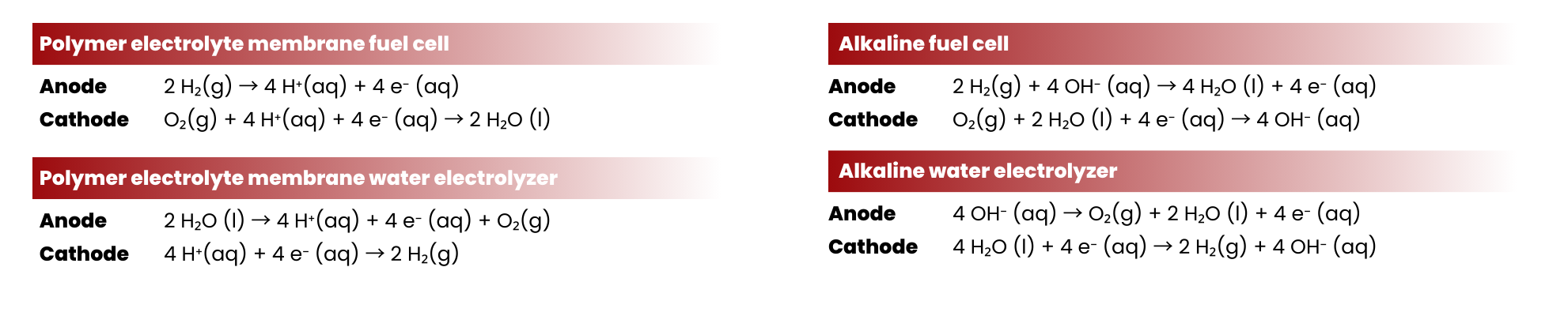
Difference between Alkaline and Proton Exchange Membranes Fuel Cells and Water Electrolyzers

Proton Exchange Members as a Core Element of PEM Water Electrolyzer and Fuel Cell
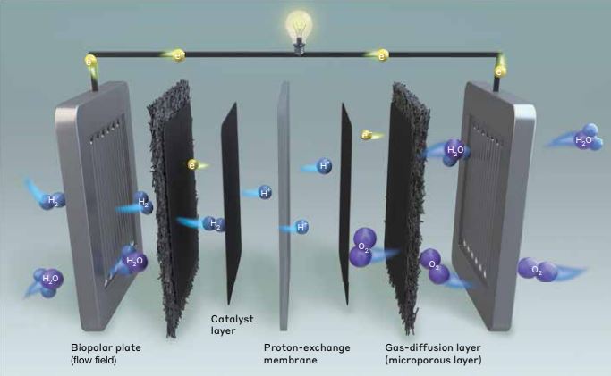
To make the electrolyzer design more compact, solid ion conducting polymers are used instead of liquid electrolytes. Solid ion conducting polymers allows the crossing of ionic species between the electrodes (anode and cathode) during the electrochemical cell operation. These ion exchange membranes are composed of a polymer backbone infused with (or functionalized) with ionic charges to allow the selective permeation of the desired ions for the reactions.
Proton exchange membrane water electrolyzers (PEMWEs) and fuel cells (PEMFCs) employ a proton-conducting solid polymer electrolyte, more commonly known as proton exchange membranes. PEMs allow the conduction of protons (positively charged carriers) across the electrodes. On top of that, using PEMWEs reduces the possibility of fuel crossover (sometimes referred to as gas crossover for fuel cells) compared when liquid electrolytes are used. Fuel crossover causes degradation of the cell components and also reduces the efficiency of the device. For example, if hydrogen crosses over in fuel cells, it might be used for competing reactions and not the hydrogen oxidation reaction, causing parasitic currents and mixed potentials on the cathode.

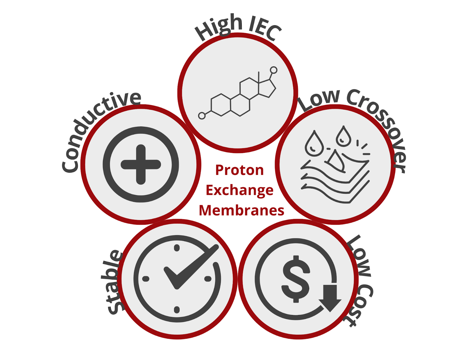
An ideal PEM possesses the following characteristics: (1) high proton conductivity, (2) high ion exchange capacity (IEC), (3) good thermal, mechanical, and chemical stability, (4) low reactant permeability, and (5) low cost. Of course, in reality, finding a PEM with all these 5 characteristics is difficult. For example, higher IECs increase proton conductivity. However, achieving a high IEC means incorporating ion exchange groups into the polymer backbone of the SPE. This makes the membrane more susceptible to chemical degradation, which in the long run reduces the proton conductivity and structural integrity of the membrane. Striking a balance between these 5 properties is critical to maximize the potential of PEMWEs and PEMFCs while ensuring long-term stability and maintaining economic viability.
Issues with the most commonly-used PEM in PEMWE and PEMFC
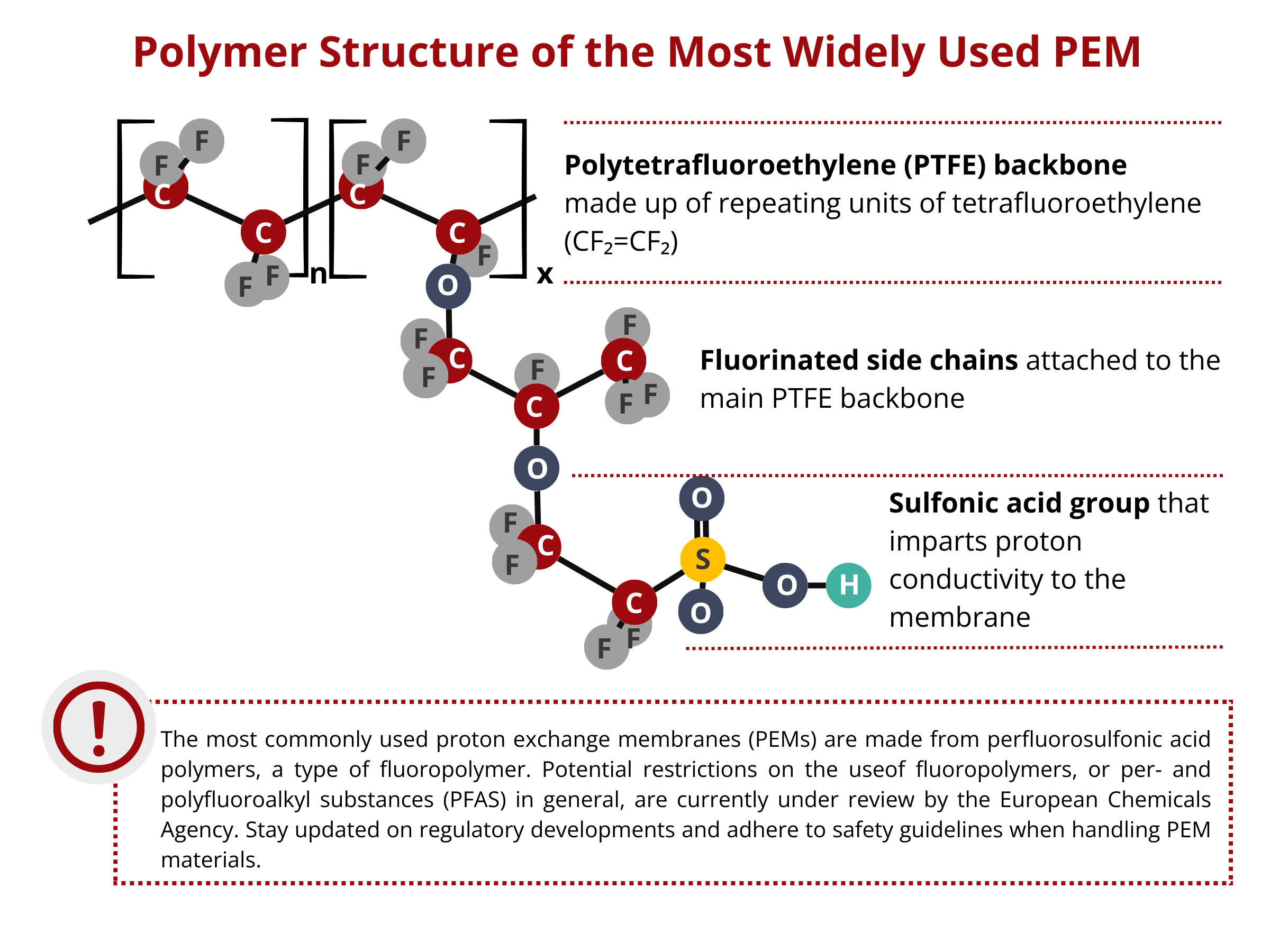
The most widely used PEMs in PEMWEs and PEMFCs are based on a perfluorosulfonic acid (PFSA) polymer with a polytetrafluoroethylene (PTFE) polymeric backbone. On one hand, the PTFE backbone confers the membrane with high chemical inertness, improving its chemical stability and reducing its reactant permeability. On the other hand, the side chains consist of sulfonic acid (–SO3H) groups that render the SPE with proton conducting capabilities. This chemistry gives this PEM high proton conductivity and excellent electrochemical and mechanical stability. However, the application of these traditional PEMs is very much limited to temperatures up to 80 °C. At higher temperatures, membrane dehydration becomes an issue for these PFSA-based membranes. As these membranes are dehydrated, a lot of interconnected ionic transfer pathways are lost, translating to a loss in the conductivity and performance of the device. Aside from that, PFSA-based membranes are expensive, which drastically affects the large-scale commercialization of PEM-based technologies, including but not limited to water electrolyzers, fuel cells, and redox flow batteries.
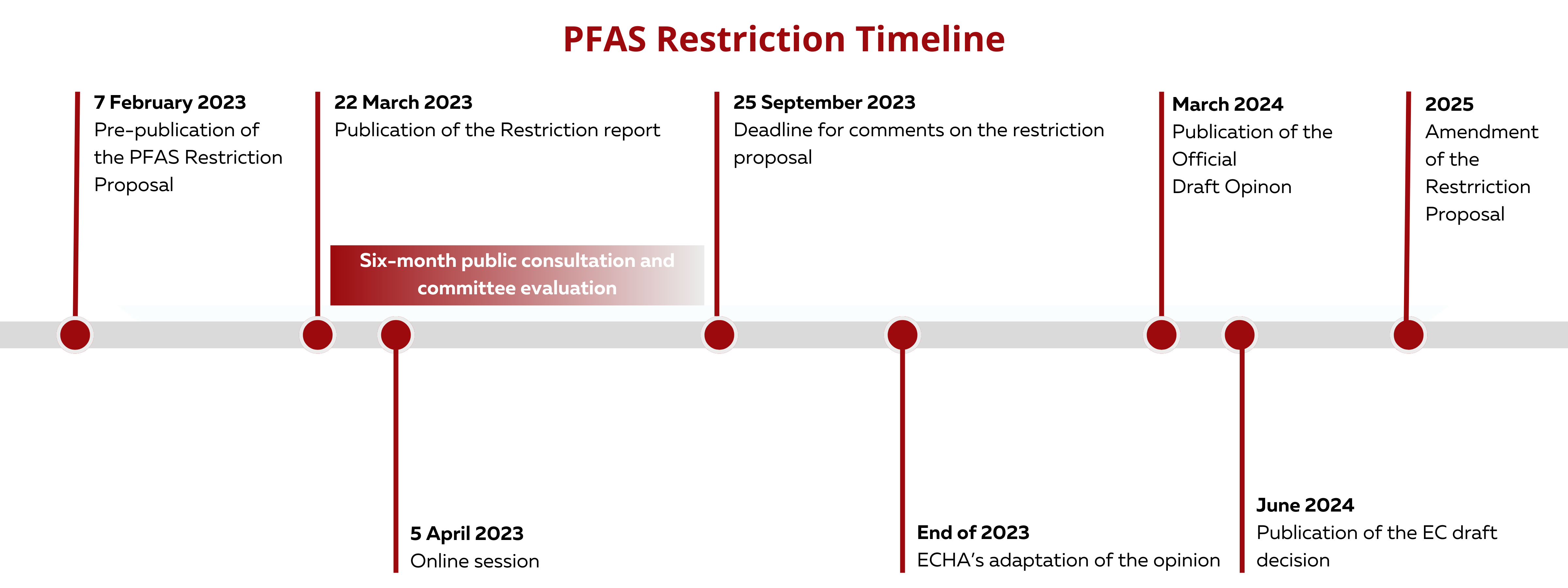
Ban on the Use of Per- and Polyfluoroalkyl Substances (PFAS)
From an environmental standpoint, using perfluorosulfonic acid-based PEMs is a matter of concern. Perfluorosulfonic acid belongs to per- and polyfluoroalkyl substances (PFAS), which are known to persist in the environment even after prolonged periods of time. The C–F bond, which is among the strongest chemical bonds, in the perfluorosulfonic acid polymers prevents the membrane from degrading completely. Due to their extreme persistence, PFAS can be easily bioaccumulated, potentially affecting human health and the environment. PFAS are known to cause cancer in humans. Some PFAS affect the human reproductive health, causing severe harm for the growth and development of fetuses and interfering with hormonal levels.
In February 2023, the European Chemicals Agency published a proposal to reduce the use of PFAS to make products and processes more safe for the human population and the environment. The proposal was led by five countries, namely Denmark, Germany, the Netherlands, Norway and Sweden. The proposal seeks to reduce the use of more than 12,000 PFAS. As PFAS are used in a wide range of industries, the idea of the proposal was not to completely eradicate the use of PFAS but to limit their usage to a minimum. A six-month consultation and scientific evaluation commenced last March 22, 2023. The risk assessment committee (RAC) will determine whether the proposed restriction indeed reduces the risk to human health and environment, whereas the socio-economic analysis committee (SEAC) will study the socio-economic impacts of the proposal. Finally, the opinions of the committees will be sent to the European Commission.
Learn more about the PFAS regulations here.
IONOMR PEMIONTM as an alternative to Perfluorosulfonic acid PEMs
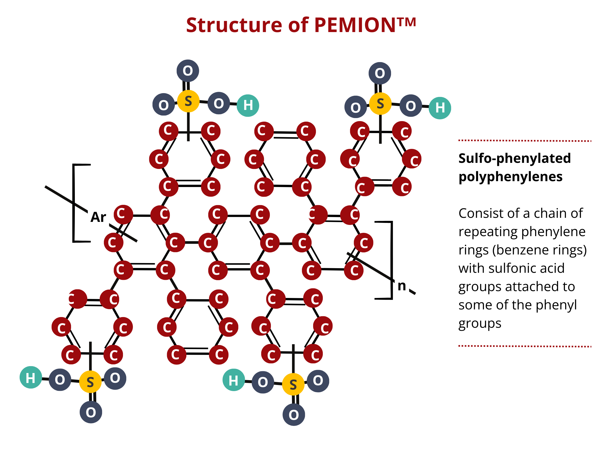
Alternative materials are sought after considering the economic, functional, and environmental problems associated with the use of perfluorosulfonic acid PEMs. IONOMR’s PemionTM proton conducting membrane is based on sulfonated polyphenylene. Polyphenylene is chemically stable, that is, it is less likely to react with other chemicals. PFAS can undergo chemical reactions under certain conditions. Additionally, polyphenylene has a greater thermal stability than that of PFAS, extending the applicability of this PEM for high-temperature PEMFC and PEMWE applications. Polyphenylene is generally less expensive to produce than some specialized PFAS compounds, reducing the overall cost of building PEMWE and PEMFC stacks.
Pemion™, a sulfo-phenylated polyphenylene, exhibits an immense potential as an alternative to PFAS-based PEMS. Case in point, the performance of Pemion™-based fuel cells approaches that of the PFSA cells under different applications. In fully humidified H2/O2 environments, MEAs containing Pemion™ achieves a peak power density as high as 2.1 W cm−2, which is comparable to that of a MEA containing optimized short-chained PFSA. Pemion™-based fuel cells outperform PFSA-based cells at elevated operating temperatures (80 °C to 110 °C) owing to the high-temperature resistance of polyphenylene. Moreover, PEMION™ exhibits an outstanding chemical stability, enduring stress tests with minimal degradation, marking a significant advancement in the development of next-generation MEA for PEMWEs and PEMFCs.
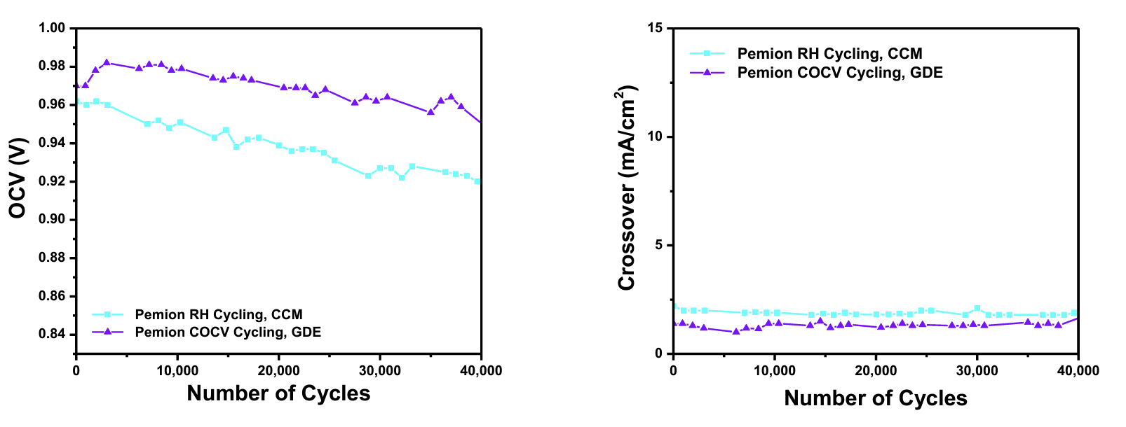
Pemion® Hydrocarbon Membranes Surpass Industry Durability Targets
Ionomr Innovations Inc.’s Pemion® hydrocarbon-based proton exchange membrane surpasses US DOE and Hydrogen Europe standards for performance and durability. Pemion® exceeded the US DOE's 20,000 cycle durability target for polymer electrolyte membranes by more than two-fold, making it the first hydrocarbon-based membrane to do so. Pemion® is ideal for heavy-duty fuel cell applications in transport, automotive, and stationary power.
Testing Method
The tests on Pemion® membranes, adhering to the DOE’s Fuel Cell Technologies Office Multi-Year Research, Development, and Demonstration Plan, ran for a minimum of 40,000 cycles. Electrochemical diagnostics were performed every 24 hours.
COCV Protocol: The COCV protocol examined chemical and mechanical stress effects by cycling the MEA from 0% RH (30 s) to 90°C dew point (45 s) at 90°C continuously until the membrane failed due to high gas crossover or met the 20,000-cycle target.
RH Cycling: The RH cycling mechanical stress tests followed the same protocol without continuous OCV hold, highlighting material capabilities against swelling and deswelling stressors. MEAs were tested using both catalyst-coated membrane (CCM) and gas diffusion electrode (GDE) configurations.
MEA Configurations: Internally fabricated CCMs used Pemion® membrane with common fuel cell catalysts (Pt/C) and ionomers (LSC PFSA), while GDE configurations used Pemion® membranes sandwiched between commercially available GDEs.
| Membrane Chemical/Mechanical Cycle and Metrics (Tests using a MEA) | |
| Cycle | Cycle 0% RH (30 s) to 90 °C dew point (45 s), single cell 25–50 cm2 |
| Total time | Until crossover >15 mA/cm2 or 20,000 cycles |
| Temperature | 90 °C |
| Relative humidity | Cycle from 0% RH (30 s) to 90 °C dew point (45 s) a |
| Fuel/oxidant | H2/air at 40 sccm/cm2 on both sides |
| Pressure | Ambient or no back pressure |
| Metric | Frequency | Target |
| F-release or equivalent for Nonfluorine membranes | At least every 24 h | No target-for monitoring |
| Hydrogen crossover (mA/cm2) | Every 24 h | <15 mA/cm2 |
| OCV c.d | Continuous | Initial wet OCV 0.95 V, <20% OCV decrease during test |
| High-frequency resistance | Every 24 h at 0.2 A/cm2 | No target-for monitoring |
| eShorting resistance | Every 24 h | >1,000 ohm cm2 |
| Pressure | Ambient or no back pressure |
Reference: US Department of Energy Multi-Year Research, Development, and Demonstration Plan (Fuel Cells)
Key Findings
Performance testing on Pemion® membranes and polymers through the US DOE's COCV and RH cycling mechanical durability protocol, demonstrated exceptional stability over 40,000 cycles with electrochemical assessments every 24 hours. Pemion® MEAs showed minimal decreases in open circuit voltage and exceptionally low and stable gas crossover. These results confirm that Pemion® membranes exceed the DOE's 20,000 cycle target for fuel cell membranes, making them ideal for heavy-duty fuel cell vehicles designed to operate for a million miles.
Non Disclosure Agreement
This is a proprietary product from Ionomr, therefore, we require a signed NDA between the end customer and Ionomr before we are able to ship out the material, either for commercial use, or research.
This is done to prevent reverse engineering and public disclosure. The NDA does not restrict patenting anything, but does include the physical materials and their composition as confidential which prevents specific disclosure in a patent or otherwise but not calling out use of an AEM including Aemion by trade name. The test results are included as confidential information, and require approval from both parties to disclose. We are not concerned about blocking any publications, but would typically advise if we believe better results can be achieved.
We have a more explicit MTA (Materials Transfer Agreement) we use with academic/research organizations which outlines more detail around materials IP and publication.
Please find the NDA here and fill it in when contacting us for quotations.